MANUAL IMPAC Pyrometers ISR 6 Advanced
Confidential Information The material contained herein consists of information that is the property of LumaSense Technologies and intended solely for use by the purchaser of the equipment described in this manual. All specifications are subject to change without notice. Changes are made periodically to the information in this publication, and these changes will be incorporated in new editions.
Contents 1 General Information...................................................................................................... 5 1.1 Information about the user manual..................................................................... 5 1.1.1 Legend ................................................................................................................. 5 1.1.2 Terminology ........................................................................................................ 5 1.2 Safety ..
.4 Transmittance t.................................................................................................... 23 4.5 Response Time (t90) .............................................................................................. 23 4.6 Clear Peak Memory (tCLEAR) ................................................................................... 23 4.6.1 Single and Double Storage Modes .................................................................... 24 4.6.2 Clear Time Settings..............
1 General Information 1.1 Information about the user manual Congratulations on choosing the high quality and highly efficient IMPAC Series 6-TV pyrometer. This manual provides important information about the instrument and can be used as a work of reference for installing, operating, and maintaining your IMPAC Series 6-TV pyrometer. It is important that you carefully read the information contained in this manual and follow all safety procedures before you install or operate the instrument.
The warranty is VOID if the instrument is disassembled, tampered with, altered, or otherwise damaged without prior written consent from LumaSense Technologies; or if considered by LumaSense Technologies to be abused or used in abnormal conditions. The Windows compatible software was thoroughly tested on a wide range of Windows operating systems and in several world languages.
Technical Support can be contacted by telephone or email: Santa Clara, California · Telephone: +1 408 727 1600 or +1 800 631 0176 · Email: support@lumasenseinc.com Frankfurt, Germany · Telephone: +49 (0) 69 97373 0 · Email: eusupport@lumasenseinc.com Erstein, France · Telephone +33 (0)3 88 98 98 01 · Email: eusupport@lumasenseinc.com 1.
To ensure consistent document formatting, this page was intentionally left blank.
2 Introduction 2.1 Appropriate use The IMPAC ISR 6 pyrometer is a stationary, digital pyrometer for non-contact temperature measurement metals, ceramics, graphite, etc. in ranges between 600 and 3000 °C. The pyrometer measures in 2-color mode (ratio principle) in which two adjacent wavelengths are used to calculate the temperature.
Optics Sighting: Optics: Distance ratio: Environment Protection Class: Operating Position: Ambient Temperature: Built-in laser aiming light (max.
Power Consumption: Load (analog output): Isolation: Max. 3 W ( incl. laser) 0 to 500 W Power supply, analog output and digital interface are electrically isolated from each other Note: The calibration / adjustment of the instruments was carried out in accordance with VDI/VDE directive “Temperature measurement in industry, Radiation thermometry, Calibration of radiation thermometers”, VDI/VDE 3511, Part 4.4. For additional details on this directive, see http://info.lumasenseinc.
2.6 Accessories (optional) Numerous accessories guarantee easy installation of the pyrometer. The following overview shows a selection of suitable accessories. You can find the entire accessory program with all reference numbers in Chapter 8, Reference numbers. 2.6.1 Mounting An adjustable mounting angle is available to easily mount the pyrometer and align it to the measured object. 2.6.
Schematic drawing of the flange system It can consist of e.g. mounting support, tube support with air purge and flange and an open or closed ceramic sighting tube. The mounting support can be equipped with a quartz window for vacuum applications. It may consist of an equipment rack, flange, and an open or closed ceramic tube. The equipment rack can be equipped for vacuum applications with a fused silica. 2.7 Transport, Packing, Storage With faulty shipping, the instrument can be damaged or destroyed.
To ensure consistent document formatting, this page was intentionally left blank.
3 Controls and Installation 3.1 Electrical Installation The pyrometer is powered by 24 V DC ± 25% (very well stabilized, ripple max. 50 mV). It is important to ensure correct polarity when connecting the device to the power supply. To meet the electromagnetic requirements (EMV), a shielded connecting cable must be used. LumaSense offers connecting cables, which are not part of the standard scope of delivery. The shield of the connecting cable has to be connected only on the pyrometer’s side.
The connector pin J can be used for 3 different functions: 1. External clearing of the maximum value storage: When the pyrometer is in operating mode, pin J can be used for external clearing of maximum value storage. When external clearing is selected from the tclear dropdown menu, pin J is connected for a short time to pin K (power supply voltage) to clear the stored maximum value. The function “external clearing” is triggered with the following conditions: · The clear time is set to “extern”.
3.1.3 Connection to RS485 Half-duplex mode: A1 and A2 as well as B1 and B2 are bridged in the 12-pin round connector of the connecting cable, to prevent reflections due to long stubs. RS485 Bus System It also safeguards against the interruption of the RS485 Bus System should a connecting plug be pulled out. The master labels mark the connections on the RS485 converter. The transmission rate of the serial interface in Baud (Bd) is dependent on the length of the cable.
Instruments like an analog controller or printer can be connected to the display in a series as shown above (total load of resistance max. 500 Ohm). 3.2 Sighting The ISR 6 Advanced can be purchased with Through-Lens Sighting or with a Laser targeting light. These sighting options allow you to easily align the pyrometer to the measuring object. 3.2.1 Viewfinder The ISR 6 Advanced can be equipped with a viewfinder which offers through-lens sighting. The viewfinder is true-sided and parallax-free.
Note: The laser warning signs on the pyrometer should be easily viewable at all times, even after it has been installed. Laser Beam Safety Warning: The instrument is equipped with a class II laser that emits radiation. To reduce the risk of injury to the eyes, do not look directly into the targeting laser and do not point the targeting laser into anyone's eyes. 3.3 Optics 3.3.1 Spot Sizes The ISR 6 Advanced has a Vario optics, which can be manually adjusted at all distances between 210 mm and 5000 mm.
Focused spot sizes between the listed distances can be found by linear interpolation between the listed values. For example, for range 600 to 1400 °C, the spot size at 1600 mm distance would be about 16 mm. Note: Effective aperture D for all temperature ranges is 12 mm (focused to longest distance) to 16 mm (focused to shortest distance). 3.3.
4 Settings / parameter descriptions The pyrometer is equipped with a wide range of settings for optimal adaptation to the required measuring condition and to measure the temperature correctly. The digital PC interface allows you to exchange data with a PC either by using the supplied InfraWin software or by using the Universal Pyrometer Protocol (UPP) commands with your own communication program (see Chapter 7 for the UPP Data Format commands).
using a thermocouple probe or by knowing one process temperature point precisely from other sources. The K-factor can then be adjusted until the pyrometer shows the same temperature value. The ISR 6 is factory calibrated for graybody targets that exhibit equal changes in emissivity within its two spectral bands. Note: Emissivity Slope K Settings: 0.800 to 1.200 in steps of 1/1000 (2-color mode). 4.3.
The table shows typical errors that can result when the emissivity of one wavelength differs from the other wavelength by only 1%. The errors can get quite large as temperatures increase. This error can be much larger than a 1-color IR pyrometer would produce for 1% emissivity change. Therefore, it is important to select the proper mode (2-color vs. 1-color) on the ISR 6 to measure a specific material.
If the maximum value storage is switched on, the highest last temperature value will always be displayed and stored. As such, it may be beneficial to periodically clear and reset the stored maximum values in order to obtain new temperature readings. This storage also has to be cleared at regular intervals when fluctuating object temperatures cause the display or the analog outputs to change too rapidly or when the pyrometer is not constantly viewing an object to be measured.
AUTO The AUTO mode is used for discontinuous measuring tasks. For example, when objects are being transported on a conveyer belt and pass the measuring beam of the pyrometer only for a few seconds. In this case, the maximum value for each object has to be obtained. With the AUTO mode, the maximum value is stored until a new hot object appears in the measuring beam. The temperature, which has to be recognized as “hot” is defined by the low limit of the adjusted sub range.
Note: Settings for Minimum Intensity Switch-Off Level: 2% to 50% Ratio pyrometers are able to measure temperatures correctly even with very low signals. If the signal is too low for a correct measurement, the pyrometer interrupts the measurement and displays 1 °C below of beginning of the temperature range. Although the factory default is set to 10%, switch-off limit can be adjusted between 2 and 50%, depending on the application.
you to program all pyrometers at the same time, regardless of the addresses that have already been assigned. If the address of a pyrometer is unknown, it is possible to communicate with it using the global Address 99 (connect only one pyrometer). 4.14 Focused Distance The focused distance value can be adjusted at all distances between 210 mm and 5000 mm using the Focus Adjustment Screw on the back of the device.
To ensure consistent document formatting, this page was intentionally left blank.
5 Software InfraWin The operating and analyzing InfraWin software is included with delivery of the pyrometer. In addition to allowing you to make parameter adjustments, the InfraWin software also provides temperature indication, data logging, and measurement analysis features. This section gives an overview about the functions of the software. It also provides a description of the individual icons found in the program's help menu.
5.4 Basic settings All preset values for the device can be displayed and modified, if necessary under the Devices/Parameters window. Changing an existing pyrometer setting can be accomplished by typing a value in an input box or by selecting a preset value from the list field. Choose the correct settings for your application from the displayed options. This window contains the parameter settings described in Chapter 4, Parameters. 5.4.1 Open/Save 5.4.2 1 measure… 5.4.3 Print 5.4.4 Close 5.4.
In the lower part of the window, the connection with the preset baud rate can be checked. Here the command was sent 100 times with 19200 baud. It has taken 0.800 seconds without transmission errors. Emi: AutoFind: If the true temperature of the measured object is known, you can calculate the emissivity of the measured object using the Emi: AutoFind function: A measured temperature is displayed with the current set emissivity (in this example 100%) (here: 707.8 °C).
5.6 Warning Level / Switch-Off Level In addition to the relative signal bar graph, the warning level and the switch-off level are indicated as vertical lines in colors corresponding to the windows below. The ISR 6 pyrometers are equipped with a warning level “dirty window” monitoring system. A correct temperature measurement might be impossible if the ratio pyrometer is working at a too low signal level.
Once the temperature entry has been entered and confirmed with OK, InfraWin will then calculate the emissivity slope. The new emissivity slope will immediately appear along with the new temperature, which can be used for further temperature measurement. 5.8 Measurement online trend The measurement function allows you to access a number of input tabs located on the left side of the screen. The main or home tab is the Output Screen. You can toggle the input tabs on and off by clicking them.
the amount of data increases, so does the amount of storage space required to save it. In order to save room, all .i12 data files are stored by a binary code. 5.10 Output .TXT file (analyzing) The same file as under Output listing may be converted into a text file and can be easily opened, for example with Microsoft Excel. With the standard import settings, Excel automatically formats the columns accordingly (with tabs as separators). 5.
5.14 Search I/O Module The I/O Module allows accessories to connect to the software and is used to trigger measurement externally or to send a signal (like a relay) under certain conditions.
To ensure consistent document formatting, this page was intentionally left blank.
6 Maintenance 6.1 Cleaning ISR 6 Window Because there are no moving parts in the ISR 6, the only regular maintenance required is a periodic inspection of the front window for build-up of foreign particles which, in time, can influence the energy received by the instrument. The ISR 6 has a “Dirty Window” warning alarm feature that can measure the current window/optical path transmission and provide a contact closure alert when the window transmission falls below the user set point.
In the 1-color (mono) mode, the pyrometer can measure objects at any distance. However, the object has to be bigger than or at least as big as the spot size of the pyrometer in the measuring distance. In the 2-color (ratio) mode, the object can be somewhat smaller than the spot diameter. Information on this topic can be found in Section 3.3 Optics and Section 4.14 Focused Distance. · Obscured window: Refer to Cleaning ISR 6 Window, Section 6.1.1.
7 Data format UPPÒ (Universal Pyrometer Protocol) Software commands can be exchanged directly with the pyrometer through an interface using suitable communication software or by using the Test function located in the Pyrometer Parameters window of the InfraWin software package.
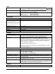
Description Command Parameters Measuring value (one-channel and ratio temperature) AAek Answer: SSSSSQQQQQ 2x5 decimal digits (in °C or °F, last digit is 1/10 °C or °F), SSSSS = one-channel temperature QQQQQ=ratio temperature Emissivity e for onechannel temperature AAemXXXX AAem XXXX=0050 to 1000 Answer: DDDD e=0.050 to 1.000 4 decimal digits 0050 to 1000 Transmittance t of window AAetXXXX AAet XXXX=0050 to 1000 Answer: DDDD t=0.050 to 1.
Description Command Parameters Read parameters AApa Answer: 15 decimal digits DD . . . . . . . . . . . . . : Emissivity . . D . . . . . . . . . . . . : Response time . . . D . . . . . . . . . . . : Clear peak memory . . . . D . . . . . . . . . . : Analog output . . . . . DD . . . . . . . . : Internal temperature . . . . . . . DD . . . . . . : Device address . . . . . . . . . 4 . . . . . . : Baud rate . . . . . . . . . . 0 , , , , : always 0 . . . . . . . . . . .
To ensure consistent document formatting, this page was intentionally left blank.
8 Reference Numbers 8.1 Reference numbers instrument Temperature Range With Viewfinder With Laser Targeting 3 904 020 3 904 080 3 904 150 3 904 220 3 904 010 3 904 070 3 904 140 3 904 210 600 to 1400 °C (MB14) 700 to 1800 °C (MB 18) 800 to 2500 °C (MB 25) 1000 to 3000 °C (MB 30) Ordering note: A connection cable is not included in scope of delivery and has to be ordered separately. 8.
3 852 550 Power supply NG 2D for DIN rail mounting; 85 to 265 V AC Þ 24 V DC, 600 mA with two settable limit switches 3 890 640 DA 4000-N: LED-digital display to be built into the switchboard 3 890 650 DA 4000: like DA 4000-N, but additionally with 2 limit switches 3 890 570 DA 6000-N digital display to allow adjustment of the Pyrometer through the RS485 interface.
9 Troubleshooting Symptom No analog output even if the display shows a temperature above lower range limit Probable Cause Reversed leads to ISR 6. Reversed leads to other instruments Comments The ISR 6 is diode protected if power leads are reversed. See section 3.1 in the current loop. Open circuit in lines connecting all instruments in current loop. Total burden higher than 500 Ohms Insufficient supply voltage (See wiring diagram).
Symptom Temperature readings are too high Probable Cause Comments Targets hotter than expected. (This often happens with first time infrared Pyrometer users). Verify target temperature with contact type method. Incorrect slope adjustments. See sections 6.3 and 5.2.4 Target size is too small See sections 3.4, 3.5, and 5.2.11 The measurement is influenced by reflections of hot machine parts Use mechanical accessories to avoid the influence of the interfering radiation.
Symptom Noisy readings (fast fluctuations). Probable Cause Comments Target moves more than 95% out of field of view. Conveyor type applications will also cause fluctuations as targets move by the field of view. Application may require Maximum to be stored. Apply tclear settings. See section 4.6.2. Target may be changing temperature quickly. (Thermocouples do not respond as fast as the ISR 6). Speed of response may be slowed down Apply t90 settings. See section 4.5.
To ensure consistent document formatting, this page was intentionally left blank.
Index 1 1 measure… 30 I A I/O Module 35 Installation 29 Installation, Electrical 15 Accesories 12 Air Purge 12 Analog Output 25 Appropriate use 9 B Basic settings 30 Baud Rate 27 C Calibration 37 Laboratory 37 On-Site 37 Cleaning the front window 37 Clear Peak Memory 23 Clear Time Settings 24 Close 30 Connecting the pyrometer to a PC 16, 29 Connection cable 9 Connection to RS485 17 Cooling Jacket 12 D Data format UPPÒ 39 Device Address 26 Device Settings Focused Distance 20 Disposal 7 Double Storage
Response Time 23 RS485 17 S Safety 5 Scaling Trend button 33 Scope of delivery 9 Service Request 6 Settings / parameter descriptions 21 Sighting 18 Single Storage Mode 24 Software InfraWin 29 Spot size calculator 34 Spot Sizes 19 Spot sizes for non-focused distances 20 Storage 13 Storage Modes 24 Sub Range 26 Support 6 T Technical Data 9 Test 30 Threshold button 33 Time interval 34 Transmittance 23 Transport 13 Trend output 34 Troubleshooting 45 TXT file 34 U Unpacking the Instrument 6 UPPÒ data format 3