MANUAL IMPAC Pyrometer IS 310 IGA 310
Confidential Information The material contained herein consists of information that is the property of LumaSense Technologies and intended solely for use by the purchaser of the equipment described in this manual. All specifications are subject to change without notice. Changes are made periodically to the information in this publication, and these changes will be incorporated in new editions.
Contents 1 General Information...................................................................................................... 5 1.1 Information about the user manual..................................................................... 5 1.1.1 Legend ................................................................................................................. 5 1.1.2 Terminology ........................................................................................................ 5 1.2 Safety ..
7 Reference Numbers ..................................................................................................... 19 7.1 Reference numbers instrument .......................................................................... 19 7.2 Reference numbers accessories .......................................................................... 19 Index ..................................................................................................................................
1 General Information 1.1 Information about the user manual Congratulations on choosing the high quality and highly efficient IMPAC pyrometer. This manual provides important information about the instrument and can be used as a work of reference for installing, operating, and maintaining your pyrometer. It is important that you carefully read the information contained in this manual and follow all safety procedures before you install or operate the instrument.
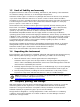
1.3 Limit of liability and warranty All general information and notes for handling, maintenance, and cleaning of this instrument are offered according to the best of our knowledge and experience. LumaSense Technologies is not liable for any damages that arise from the use of any examples or processes mentioned in this manual or in case the content of this document should be incomplete or incorrect.
1.6 Service Request, Repair, or Support Contact LumaSense Technologies Technical Support in case of a malfunction or service request. Provide clearly stated details of the problem as well as the instrument model number and serial number. Upon receipt of this information, Technical Support will attempt to locate the fault and, if possible, solve the problem over the telephone.
1.8 Disposal / decommissioning Inoperable IMPAC pyrometers must be disposed of in compliance with local regulations for electro or electronic material.
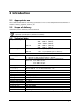
2 Introduction 2.1 Appropriate use The IS 310 and IGA 310 are stationary pyrometers for non-contact temperature measurement of metallic surfaces, graphite, ceramics, etc. 2.2 Scope of delivery Instrument, works certificate, and user manual. Note: A connection cable is not included with the instrument and has to be ordered separately (see Chapter 7, Reference numbers). 2.3 Technical data Temperature ranges: Spectral Range: Power supply: IS 310 650 ... 1800 °C (MB 18) 800 ...
Note: The calibration / adjustment of the instruments was carried out in accordance with VDI/VDE directive “Temperature measurement in industry, Radiation thermometry, Calibration of radiation thermometers”, VDI/VDE 3511, Part 4.4. For additional details on this directive, see http://info.lumasenseinc.com/calibration or order the directive from “Beuth Verlag GmbH” in D-10772 Berlin, Germany. 2.4 Dimensions All dimensions in mm *) D: Aperture dependent on instrument type, see Section 3.3 Optics 2.
3 Controls and Installation 3.1 Electrical Installation The instruments are supplied by 24 V DC ( 25%) and a ripple < 50 mV. Ensure correct polarity when connecting the instrument to the power supply. The power consumption (in this case, 4 ... 20 mA) is also the measuring signal. The instrument doesn’t need any time for starting or preheating and is immediately ready for operation. To switch off the instrument, interrupt the instrument’s power supply.
3.1.2 Calculation of the measuring temperature from current output IS 310 IS 310 IS 310 MB 18 MB 23 MB 25 Temp. [°C] = Temp. [°C] = Temp. [°C] = 71.875 current [mA] + 362.5 93.750 current [mA] + 425 87.500 current [mA] + 750 IGA 310 IGA 310 MB 13L MB 15 Temp. [°C] = Temp. [°C] = 62.500 current [mA] + 50 62.500 current [mA] + 250 3.2 LED targeting light The pyrometers are equipped with an LED targeting light for aiming onto the measuring object. The center of the light marks the center of the spot.
4 Parameter descriptions / Settings 4.1 Emissivity For a correct measurement, it is necessary to adjust the emissivity . This emissivity is the relationship between the emission of a real object and the emission of a black body radiation source (this is an object which absorbs all incoming rays and has an emissivity of 100%) at the same temperature. Different materials have different emissivities ranging between 0% and 100% (settings at the pyrometer between 0.2 ... 1, equivalent to 20 … 100%).
To ensure consistent document formatting, this page was intentionally left blank.
5 Maintenance 5.1 Safety If the pyrometer is integrated into a running machine process, the machine has to be switched off and secured against restart before servicing the pyrometer. 5.2 Service The pyrometer has no serviceable internal parts. The lens can be cleaned with compressed air, which is dry and free of oil. If the lens requires a more thorough cleaning, use a soft, dry cloth (such as a clean camera lens cloth).
To ensure consistent document formatting, this page was intentionally left blank.
6 Troubleshooting Before sending the pyrometer for repair, try to find the error and to solve the problem with the help of the following list. Temperature indication too low Incorrect alignment of the pyrometer to the object New correct alignment to achieve the max. temperature signal Measuring object is smaller than spot size Check measuring distance, smallest spot size is at nominal measuring distance (see 3.3) Emissivity set too high Set lower correct emissivity corresponding to the material (see 4.
To ensure consistent document formatting, this page was intentionally left blank.
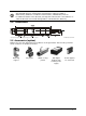
7 Reference Numbers 7.1 Reference numbers instrument Temperature Range Pyrometer Optics a = 250 mm a = 600 mm a = 1400 mm IS 310 650 … 1800 °C (MB 18) 800 … 2300 °C (MB 23) 1100 … 2500 °C (MB 25) 3 902 210 3 902 220 3 902 230 3 902 250 3 902 260 3 902 270 3 902 310 3 902 320 3 902 330 Temperature Range Pyrometer IGA 310 7.
Flange system: 3 846 240 3 846 280 3 846 250 Tube support with air purge and flange Ceramic tube 24, 600 mm long, closed Support for instrument IS 310 / IGA 310 Manual Reference Numbers 20
Index A Accessories 10 Analyzing devices 11 Appropriate use 9 C Calculation of the measuring temperature 12 Changing of optics or fiber 15 Controls and Installation 11 D Disposal 8 E Electrical connection 5 Electrical Installation 11 Emissivity 13 G General Information 5 I Installation Electrical 11 R Reference numbers Accessories 19 Instrument 19 Reference Numbers 19 Repair 7 S Safety 5 Scope of delivery 9 Service Request 7 Settings / parameter descriptions 13 Shield 11 Storage 6 Support 7 T Techni