
Manual


Chapter 12
______________________________________________________________________
_____________________________________________________________________________
BE6030-13 1314i Photoacoustic Gas Monitor LumaSense Technologies A/S
Page 168 of 199
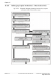
12.9.2 Performing a Span Calibration – Stand-alone Use
The general equipment necessary to perform a calibration task is
described in section 12.4. Follow the procedure from step 1 to step 3
inclusive and then continue as follows:
1.
a. Connect the free-end of the Teflon tubing mentioned in step 3
to the pressure valve on a cylinder of calibration gas.
b. Press
↵
.
c. Gently open the pressure-valve on the gas cylinder and
regulate the flow of gas so that when the Monitor’s pump is
running there is a positive flow of gas out of the flow meter.
This will ensure that the calibration gas is not diluted by
atmospheric air.
The following text appears on the screen:
RESULTS NOT YET AVAILABLE
PLEASE WAIT
Once the first measurement result is available the screen text
illustrated above is replaced by a screen displaying the
measurement results – for example the following:
W : µ : 5.34 µV σ : 212 nV 3 40.4 °C
PRESS ENTER WHEN RESULTS ARE STABLE
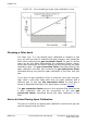
As soon as measurement results are available, they not only
appear on the display (see Fig.12.12) but are automatically
printed out on the printer, if the Monitor has been set up to print
a data log, see section 10.5. Remember to turn off the data log
when the calibration is complete.
Each time a sample of gas is drawn into the analysis cell the
signal is measured using both optical filter “A” and the water-
vapour filter (“W”) but, due to lack of space on the display, the
Monitor only displays the signal measured using the water-vapour
filter. The data-log print-out, however, shows the signal measured
using both the water-vapour filter and filter “A”. If cross-
compensation calibration was also selected in the calibration
set-up, then the signal is measured in the cell using all the
installed filters.
A maximum of 6 measurements are stored in the Monitor during
any calibration. The number (n) indicates how many
measurements are stored. When 7 measurements have been