User Manual for 1309 Multipoint Sampler BE1285-15
Index ________________________________________________________________________ Index Index ................................................................................................................................... 2 1309 Multipoint Sampler ........................................................................................................ 3 SAFETY CONSIDERATIONS .................................................................................................. 4 Safety Considerations ..........
1309 ________________________________________________________________________ 1309 Multipoint Sampler From Serial number: 660-128 November 2011 ________________________________________________________________________ BE1285-15 1309 Multipoint Sampler LumaSense Technologies A/S Page 3 of 42
Safety Considerations ________________________________________________________________________ Safety Considerations SAFETY CONSIDERATIONS PLEASE READ THESE SAFETY CONSIDERATIONS CAREFULLY AND MAKE SURE YOU UNDERSTAND THEM PROPERLY BEFORE YOU START OPERATING THE 1309 MULTIPOINT SAMPLER. EXPLOSION HAZARD THE 1309 MULTIPOINT SAMPLER IS NOT DESIGNED FOR USE IN POTENTIALLY EXPLOSIVE ENVIRONMENTS. This means that the instrument must not be placed and operated in an area with a potentially explosive atmosphere.
Safety Considerations ________________________________________________________________________ SAFETY CONSIDERATIONS The 1309 Multipoint Sampler complies with EN/IEC 61010-1 3rd Ed. (2010): Safety requirements for electrical equipment for measurement, control and laboratory use. To ensure safe operation and retain the 1309 in safe condition, note the following: APPLYING POWER Before using the 1309 check that the available mains voltage match the specified voltage and frequency for the instrument.
Chapter 1 ________________________________________________________________________ Chapter 1 Description and Functions November 2011 ________________________________________________________________________ BE1285-15 1309 Multipoint Sampler LumaSense Technologies A/S Page 6 of 42
Chapter 1 ________________________________________________________________________ 1.1 Description and Function 1.1.1 The Sampler System The pneumatic system of the 1309 is shown schematically in Fig.1.1. The sampler system is constructed of stainless steel (AISI 316) and PTFE (PolyTetraFluoroEthylene) tubing to minimize adsorption of samples. The system has 12 inlet channels, each with a solenoid valve.
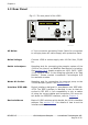
Chapter 1 ________________________________________________________________________ 1.2 Front Panel Fig.1.2 The front panel of the 1309 Sampler: 12 mounting stubs for connection of tubing to sampling points. Each stub is numbered, and has a correspondingly-numbered lamp. When the lamp is lit, it indicates that the corresponding sampling valve is open, see section 3.3. The Analyzer/Waste Air lamps indicate which way the internal 3 way valve is set, see section 3.3.
Chapter 1 ________________________________________________________________________ 1.3 Rear Panel Fig.1.3 The rear panel of the 1309 100 - 240 Vac Fuses: T1.6AL 50-60Hz 70VA 00061-02-110311 AC Mains: A 3-pin connector accepting Power Cable for connection to a single phase AC mains supply with protective Earth. Mains Voltage: Connect 1309 to mains supply with 100-240 Vac, 50/60 Hz.
Chapter 2 ________________________________________________________________________ Chapter 2 Preparing to Use the 1309 November 2011 ________________________________________________________________________ BE1285-15 1309 Multipoint Sampler LumaSense Technologies A/S Page 10 of 42
Chapter 2 ________________________________________________________________________ 2.1 Preliminary 2.1.1 Environment and Handling The Type 1309 Multipoint Sampler is designed for use in environments with temperatures between +5°C and +40°C (+41°F and +104°F) and with up to 90% relative humidity (non-condensing) at 40°C. Make sure to leave some space between the Rear Panel and the Wall, or other obstacles, to ensure easy access to the mains supply. No other special handling precautions are necessary. 2.1.
Chapter 2 ________________________________________________________________________ Again using the screwdriver, gently lever the fuse-holders out from their slots. See Fig. 2.2. Fig.2.2. Inserting the fuses into the 1309’s fuse holder Use two 1.6A slow-blow fuses (LumaSense No. VF0007), they are supplied with the instrument. When replacing the fuse-holders, ensure that the direction of the white arrows on each holder matches the arrows marked on the covering flap. 2.
Chapter 2 ________________________________________________________________________ 2.3 System Use The 1309 combined with a Gas Monitor and a controlling computer provides a system that offers wide-ranging monitoring capabilities. The 1309 makes it possible to perform multipoint monitoring tasks in many different situations and environments, without changing the system components. An example of a multipoint, multi-gas monitoring system is shown in fig. 2.3.
Chapter 2 ________________________________________________________________________ 2.3.1 Setting the Interface Address of the 1309 The 1309 uses a single interface address. The address is set using the bank of eight DIP switches on the rear panel of the 1309. The last five switches on the bank decide the interface address. These switches are marked A1 (the least significant bit) to A5 (the most significant bit).
Chapter 2 ________________________________________________________________________ Fig. 2.5. Dipswitch settings binary “0” If the switch is up, it represents a binary “1”. See Fig. 2.6. Fig. 2.6 Dipswitch settings binary “1” The default interface address of the 1309 is set to 01111 (decimal value 15), see Fig. 2.7. If this is not suitable for your system, use the switches to set an address appropriate to your system.
Chapter 2 ________________________________________________________________________ Fig. 2.7. Interface address 15 2.4 Connecting Tubing to the 1309 The 1309 is connected via tubing to: the sampling points; to the gas-monitor being used to analyse the gases that are sampled; to the external pump. Note: the performance of the 1309’s sampling system is dependant on the type of external pump used and the length and diameter of the sampling tubing.
Chapter 2 ________________________________________________________________________ ronment of the instrument so it maintains either the same temperature, or a lower temperature than the instrument. See section 2.4.3 for details of how to fit a water-trap filter. 2.4.1 Connecting Sampling Tubing Before connecting sampling tubing to the 1309, determine approximately where the sampling points will be in the area to be monitored.
Chapter 2 ________________________________________________________________________ 2.4.2 Connecting External Filters to the Sampling Tubes The external filters, comprising filter, LumaSense accessory number DS2306, and fitting, LumaSense accessory number UD5041 (optional accessories), protect the 1309’s sampling airways from airborne particles such as dust, thus helping to prevent blockage of the airways. The filter unit is attached to the tubing as follows (see Fig.2.9): Fig.2.
Chapter 2 ________________________________________________________________________ Note: some gases may be absorbed by the water trapped in the filter. This will reduce the gases’ concentrations. To connect sampling tubing to the water-trap filter Push the sampling tubing into the connector as far as it will go and tighten the nut. Fig. 2.10 Attaching tubing to the In-line Genie Membrane Separator.
Chapter 2 ________________________________________________________________________ The Waste Air Outlet stub, next to the Outlet to Analyzer, (see fig. 1.3) stub on the rear panel of the 1309, connects the external pump to the 1309’s sampler system. If you do not wish the waste air from the pump to mix with the air in the room where the 1309 is positioned, connect a length of PTFE tubing (LumaSense no.
Chapter 3 ________________________________________________________________________ Chapter 3 Operation November 2011 ________________________________________________________________________ BE1285-15 1309 Multipoint Sampler LumaSense Technologies A/S Page 21 of 42
Chapter 3 ________________________________________________________________________ All tasks performed by the 1309 are controlled over the IEEE/IEC interface from a System Controller; there is no other control possibility. This chapter deals with the control of the 1309 from the user’s point of view; for details of the IEEE/IEC interface specifications, refer to Chapter 4 of this manual. Sections 3.1 and 3.2 deal with switching-on and the general principles of controlling the 1309. Sections 3.3 to 3.
Chapter 3 ________________________________________________________________________ Fig.3.1. General syntax diagram for interface jobs Job Headers The job header specifies the function you want the 1309 to perform. It consists of one or more words. The ASCII underline character “_” is used to separate individual words in the job header. For example: OPEN_SAMPLING_VALVE A hyphen “-“ or a full stop”.” can also be used to separate words in the job header.
Chapter 3 ________________________________________________________________________ Numerical data for interface jobs sent to the 1309 can be in NR1, NR2 or NR3 form. This is a format for describing how the numerical data is represented, for example: NR1 data: 250 (number without decimal fraction or exponent) NR2 data: 249.85 (number with decimal fraction, without exponent) NR3 data: 2.499E-2 (number with fraction and exponent).
Chapter 3 ________________________________________________________________________ Table 3.1. The range of ASCII terminator-characters which can be used in communication with the 1309 ASCII Character SOH STX ETX EOT ENQ ACK BELL BS HT LF VT FF SO SI DLE 3.2.
Chapter 3 ________________________________________________________________________ tion 4.2. The default terminator character used is the control character “”. The terminator character can be changed, as described in section 3.2.1. 3.3 Using the Sampler System Using the 1309’s sampler system, see Fig. 1.1, to deliver a sample to the Gas Monitor is a 3-stage process: 1. The required sample valve is opened; all other sample valves are closed automatically. 2.
Chapter 3 ________________________________________________________________________ The time taken to draw a sample depends upon the type of external pump and the diameter and length of the sampling tube. 3.
Chapter 3 ________________________________________________________________________ Table 3.2. The 1309’s Status Flag. Each bit represents a particular 1309 component; when set, the 1309 is currently using that component. Bit no. 1 2 3 4 5 6 7 8 9 10 11 12 13 14 15 16 Status Flag Dec.
Chapter 3 ________________________________________________________________________ 3.7 Error Conditions and Service Requests If an error arises in the 1309’s hardware, processor system or software, the 1309 can signal the system controller by generating a Service Request. The exact nature of the error condition can then be investigated by using the Warning? or Error? interface jobs. 3.7.
Chapter 3 ________________________________________________________________________ 3.7.2 Enabling Service Requests The specified bits in the status byte are enabled using the interface job Service_Request_Enable. The required bits are specified by using the decimal equivalent of their binary value, as shown in Table 3.3. See also the job examples below for further clarification.
Chapter 3 ________________________________________________________________________ 3.7.4 The Warning? Interface Job This job reads-out an 8-bit byte (the Warning Flags) which gives information about error conditions which affect the efficient operation of the 1309. The 1309 is still able to operate, but the error should be rectified as soon as possible. The Warning Flag byte is shown in Table 3.4. Table 3.4 The 1309’s Warning Flags byte Bit no. 1 2 3 4 5 6 7 8 WARNING FLAGS Dec.
Chapter 3 ________________________________________________________________________ Power Fail Flag Is set if the power is outside the range 13.25V to 15.75V. This flag is reset when the voltage is back within the above range, or by resetting the 1309, or switching the 1309 off and then on. If the error is persistent, have the 1309 serviced. 3.7.5 The Error? Interface Job This job reads-out an 8-bit byte (the Error Flags) which gives information about errors which cause the 1309 to stop working.
Chapter 3 ________________________________________________________________________ RAM Flag Indicates that the RAM (random access memory) of the 1309, which stores the 1309’s set-up data, has been corrupted. The flag is reset by switching the 1309 off and then on. If the error persists, have the 1309 serviced. PROM Flag Indicates that the CRC (cyclic redundancy check) for the PROM (programmable read-only memory) has identified incorrect data. The flag is reset by switching the 1309 off and then on.
Chapter 4 ________________________________________________________________________ Chapter 4 The IEEE/IEC Interface and Interface Job Overview November 2011 ________________________________________________________________________ BE1285-15 1309 Multipoint Sampler LumaSense Technologies A/S Page 34 of 42
Chapter 4 ________________________________________________________________________ 4.1 Introduction The digital interface of the 1309 Multipoint Sampler is designed according to ANSI/IEEE Std 488-1978, “IEEE Standard Digital Interface for Programmable Instrumentation”.
Chapter 4 ________________________________________________________________________ Section 2.4 Acceptor Handshake (AH) Interface Function, (Clause 7) AH 1 – complete capability Section 2.5 Talker (T) Interface Function, (Clause 8) T 5 – basic talker, serial poll, talk only mode, unaddress if MLA Section 2.6 Listener (L) Interface Function, (Clause 9) L 3 – basic listener, listen only mode, unaddress if MTA Section 2.
Chapter 4 ________________________________________________________________________ 4.2.1 Sampler System Jobs These jobs control the 1309’s sampler system. Further information about these jobs is given in section 3.3. Table 4.1 The interface jobs which control the 1309’s sampler system Job Header Open_Sampling_Valv e Connect_Sampling_Valv e 4.2.
Chapter 4 ________________________________________________________________________ 4.2.4 1309 Check Jobs Table 4.4 The interface jobs which check the 1309’s functions. Job Header Status? Data No data. Reset_System No data. Effect on 1309 Reads-out the 1309’s status-flag. Resets the 1309. For further information, refer to section 3.6. 4.2.5 Error Condition and Service Request Jobs These jobs allow the identification of error conditions in the 1309. For further information, refer to section 3.7.
Chapter 4 ________________________________________________________________________ Table 4.6 Standardised interface jobs which perform various secondary functions of the 1309. Job Header Define_Terminator Data Decimal value of the ASCII control character Identify? Output_Header No data EXclusive Inclusive *IDN? No data. *RST No data. *SRE *SRE? No data *STB? No data *TST? No data Effect on 1309 Selects the terminator character for interface jobs.
Chapter 5 ________________________________________________________________________ Chapter 5 Maintenance November 2011 ________________________________________________________________________ BE1285-15 1309 Multipoint Sampler LumaSense Technologies A/S Page 40 of 42
Chapter 5 ________________________________________________________________________ 5.1 Cleaning the Instrument It is recommended to clean the Instrument using a soft damped cloth. 5.2 Service and repair The Type 1309 Multipoint Sampler is designed and constructed to provide the user with many years of safe, trouble-free operation.
1309 LumaSense Technologies A/S Energivej 30 DK-2750 Ballerup, Denmark Tel.:(+45) 44 20 01 00 Fax: (+45) 44 20 01 01 http://www.lumasense.