OPERATION MANUAL IMPAC Pyrometer IN 6/78-L
Confidential Information The material contained herein consists of information that is the property of LumaSense Technologies and intended solely for use by the purchaser of the equipment described in this manual. All specifications are subject to change without notice. Changes are made periodically to the information in this publication, and these changes will be incorporated in new editions.
Contents 1 General........................................................................................................................... 5 1.1 Information about the user manual..................................................................... 5 1.1.1 Legend ................................................................................................................. 5 1.1.2 Terminology ........................................................................................................ 5 1.
.8 4.9 4.10 4.11 5 Software InfraWin ....................................................................................................... 21 5.1 5.2 5.3 5.4 5.5 5.6 5.7 5.8 5.9 5.10 5.11 6 Address ................................................................................................................ 19 Ambient temperature compensation................................................................. 19 Wait time tw ..............................................................................
1 General 1.1 Information about the user manual Congratulations on choosing this high quality and highly efficient IMPAC pyrometer. This manual provides important information about the instrument and can be used as a work of reference for installing, operating, and maintaining your pyrometer. It is important that you carefully read the information contained in this manual and follow all safety procedures before you install or operate the instrument.
1.2.2 Electrical Connection Follow common safety regulations for main voltage (230 or 115 V AC) when connecting additional devices. Touching the main voltage can be fatal. An incorrect connection and/or mountaing can cause serious health or material damages. Only qualified specialists are allowed to connect such devices to the main voltage. 1.
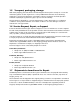
1.5 Transport, packaging, storage With faulty shipping, the instrument can be damaged or destroyed. To transport or store the instrument, please use the original box or a box padded with sufficient shock-absorbing material. For storage in humid areas or shipment overseas, the device should be placed in welded foil (ideally along with silica gel) to protect it from humidity. The pyrometer is designed for a storage temperature of -20 to 80 °C with non-condensing conditions.
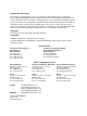
Send RMA Shipments to your nearest technical service center: Customers in North America should send RMA Shipments to: All other customers should send RMA Shipments to: Santa Clara, California Frankfurt, Germany LumaSense Technologies, Inc. 3301 Leonard Court Santa Clara, CA 95054 USA Telephone: (408) 727-1600 1-800-631-0176 LumaSense Technologies GmbH Kleyerstr. 90 60326 Frankfurt Germany Telephone: +49 (0) 69-97373 0 Email: support@lumasenseinc.com Email: support@lumasenseinc.com 1.
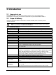
2 Introduction 2.1 Appropriate use 2.2 Scope of delivery The IMPAC IN 6/78-L is a stationary pyrometer created for non-contact temperature measurement of thin glass surfaces with a temperature range between 400 and 1100 °C. Instrument, PC measurement and evaluation software InfraWin, works certificate, and an operation manual. Note: A connection cable is not included with the instrument and has to be ordered separately (see Chapter 8, Reference numbers). 2.
Repeatability: 1 °C (Note: the pyrometer must be operate at least 30 min before these values are valid) (ε =1, t 90=1 s) Noise Equivalent Temperature / °C NETD at t90 = 80 ms / °C NETD at t90 = 1 s / °C 0.3 0.1 Temperature Difference 500 0.3 0.1 800 (NETD) s = 1 (e = 1, Tamb. = 44 °C) Protection class: Operation position: Operating temperature on housing surface: Storage temperature: Rel.
2.4 Physical User Interface 2.5 Accessories (optional) Numerous accessories guarantee easy installation of the pyrometer. The following overview shows a selection of suitable accessories. You can find the entire accessory program with all reference numbers in Chapter 8, Reference numbers). 2.5.1 Mounting For easy mounting and aligning the pyrometer to the measured object an adjustable mounting angle is available. Mounting angle 2.5.2 Cooling 2.5.
2.5.4 Displays For temperature indication of the pyrometer LumaSense offers several digital displays which can also be used for remote parametrizing (DA 6000) of the pyrometer.
3 Controls and Connections 3.1 Electrical Installation Series 6 pyrometers are powered by a voltage of 24 V DC nominal (possible range 18 to 30 V DC, ripple < 0.5 V). It is important to ensure correct polarity when connecting the device to the power supply. To meet the electromagnetic requirements (EMV), a shielded connecting cable must be used. LumaSense offers connecting cables, which are not part of the standard scope of delivery.
3.2 Connecting the pyrometer to a PC The pyrometer is equipped with a RS485 serial interface. With the RS485, long transmission distances can be realized and the transmission is, to a large extent, free of problems. The RS485 also allows several pyrometers to be connected in a bus system. If a RS485 connection is not available at the PC, it can be accomplished using the RS485 to USB connector.
3.3 Sighting For exact measurement of the object temperature the pyrometer must be aligned correctly onto the object. Pyrometers without sighting are normally used for measurement of bigger objects for which exact alignment is not absolutely necessary. These pyrometers can be aligned only with the thermal method. 3.3.
3.5 Avoiding reading errors caused by faulty assembly To avoid reading errors, please note the following points when mounting the pyrometer: 1. The diameter of the measuring object cannot be smaller than the pyrometer’s spot size (see section 3.4, Optics). 2. A source of radiation behind or around the measuring object can influence the result. If the object is transparent or partly transparent, another material behind the object could transmit its radiation to the pyrometer as well.
4 Settings / parameter descriptions Before using the pyrometer some basic settings should be taken. The basic settings can be done via interface and software InfraWin. Settings via serial interface: The pyrometer is equipped with a serial interface RS485 which can be used for connection to a PC.
One way to determine an accurate emissivity value for a material is to make a comparison measurement as follows: If possible, coat a portion of the object with dull black paint or carbon soot. Paint and carbon soot have high emissivity (95%) and take on the same temperature as the object. Measure the temperature of the painted area with the emissivity control set to 95%.
Single storage: The single storage mode is used when you want to reset the stored value using your own software with the clear command “lx”. This mode allows a new value to be established after each impulse from the reset signal. Double storage: The double storage mode is automatically selected when entering the reset intervals using the PC interface. This mode utilizes two memories in which the highest measured value is held and is deleted alternately in the set time interval (clear time).
reflected. For bright, smooth surfaces, such as mirrors, the reflected radiation is more focused; on rough, harsh surfaces it is diffuse. The rate of diffuse reflection is, in this case (100% - e). If the measured object’s temperature is the same as the ambient temperature (this is most often the case), you only need to set the emissivity on the pyrometer (when using the InfraWin program the off-set compensation for the ambient temperature must be in “auto“.
5 Software InfraWin The operating and analyzing InfraWin software is included with delivery of the pyrometer. In addition to allowing you to make parameter adjustments, the InfraWin software also provides temperature indication, data logging, and measurement analysis features. This section gives an overview about the functions of the software. It also provides a description of the individual icons found in the program's help menu.
5.4 Basic settings All preset values for the device can be displayed and modified, if necessary under the Devices/Parameters window. This window contains the parameter settings described in Chapter 4, Parameters. Changing an existing pyrometer setting can be accomplished by typing a value in an input box or by selecting a preset value from the list field. Choose the correct settings for your application from the displayed options. Once a value is changed, it is transferred to the pyrometer immediately.
Emi: AutoFind: If the true temperature of the measured object is known, you can calculate the emissivity of the measured object using the Emi: AutoFind function: A measured temperature is displayed with the current set emissivity (in this example 100%) (here: 416.1 °C). If you press Emi: Autofind a window will open which allows you to enter the "true" temperature (here 430 °C).
Note: The measuring values of “measurement online trend” are automatically saved as "standard.i12". Should you need to edit the data later, you need to save the file as another .i12-file because old values are over-written when a new measurement is taken. Files from older program versions (.i10-files) can be opened and saved as .i12. 5.6 Listing (analyzing) For analyzing the measured values in this field, all measured data appears in a numeric list.
Note: The last reading is saved in the standard.i12 file and automatically appears in this form upon opening Listing or Trend output. Selecting file open with another file, the previous file will be overwritten and replaced by the standard.i12 file. 5.9 PC sampling rate (time interval between two measurements) This function sets a time interval. After each interval, one measured value is stored on the PC. Longer time intervals will result in creating smaller stored file sizes.
To ensure consistent document formatting, this page was intentionally left blank.
6 Maintenance 6.1 Safety Attention during pyrometer services: Should the pyrometer be integrated in a running machine process, the machine should be switched off and secured against restart before servicing the pyrometer 6.2 Service The pyrometer does not have any parts which require regular service, only the lens has to be kept clean. The lens can be cleaned with a soft cloth in combination with alcohol (do not use acid solutions or dilution).
To ensure consistent document formatting, this page was intentionally left blank.
7 Data format UPP (Universal Pyrometer Protocol) Via interface and suitable communication software or via Test function of the InfraWin software (see Section 5.4 Basic settings) commands can be exchanged directly with the pyrometer. The data exchange occurs in ASCII format with the following transmission parameters: The data format is: 8 data bits, 1 stop bit, even parity (8,1,e). The device responds to the entry of a command with: output (e.g.
Description Reading basic temperature range: Command AAmb Reading temperature sub range: Repeatedly reading measuring values: AAme Parameters Output: YYYYZZZZ (hex 8-digit, °C or °F) YYYY = beginning of temp. range ZZZZ = end of temp. range as with mb AAmsXXX XXX = 000 to 999 XXX = No.
Description Reading marginal values: Device type: Serial number: Command AAmi? Parameters Output: marginal value for entry, always 01 AAna AAsn Output: “IN 6/78-L” (16 ASCII-characters) Output: XXXXX (5-digit decimal) Reference number: Device model/ Software version: AAbn AAve Output: XXXXXX (6-digit hex) Output: XXYYZZ (6-digit decimal) XX = 79 (IN 6/78-L) YY = month of the software version ZZ = year of the software version Note: the letter “l” means the lower case letter of “L”.
To ensure consistent document formatting, this page was intentionally left blank.
8 Reference numbers 8.1 Reference numbers instrument Type Temperature Range Reference Number IN 6/78-L 400 ... 1100 °C 3 906 010 Ordering note: A connection cable is not included in scope of delivery and has o be ordered separately. 8.
To ensure consistent document formatting, this page was intentionally left blank.
9 Troubleshooting Before sending the pyrometer for repair, try to find the error and to solve the problem with the help of the following list. Temperature indication too low · Incorrect alignment of the pyrometer with the object Þ Realign to achieve the maximum temperature signal(see 3.3) · Measuring object smaller than spot size Þ check measuring distance, smallest spot size is at nominal measuring distance (see 3.
To ensure consistent document formatting, this page was intentionally left blank.
Index A Accessories 11, 33 Cooling 11 Displays 12 Miscellaneous 11 Mounting 11 Address 19 Ambient temperature compensation 19 Analog output 18 Analyzing devices, additional 14 Appropriate use 9 Installation 21 Installation, electrical 13 Internal Temperature 20 L Legend 5 Listing (analyzing) 24 M Maintenance 27 B O Basic settings 22 Baud Rate 19 Baudrate 14 Optics 15 C Packaging 6 Parameter descriptions 17 Physical User Interface 11 Pin assignment of the male socket 13 Program start 21 Clear time
T Technical data 9 Thermal Alignment 15 Time interval 25 transmittance 18 Transmittance t 18 Transport, packaging, storage 6 Trouble shooting 35 TXT file 24 U Unpacking the Instrument 6 UPP data format 29 W Wait time 20 Warranty 6 IN 6/78-L Operating Manual Index · 38