
Manual


Starting Up
KLEIBER 740 17
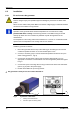
Fig. 9 Pyrometer wire connection with configuration
Connector A Meaning
Pin 1 Supply voltage +24 V (DC or AC)
Pin 2 Supply voltage 0 V (DC or AC)
Pin 3 ground output
Pin 4 Analogue output [0 (4) … 20] mA
Pin 5 empty
Connector B Meaning
1 - white Supply voltage +24 V (DC or AC)
2 - brown Supply voltage 0 V (DC or AC)
3 - green ground output
4 - yellow Analogue output [0 (4) … 20] mA
5 – green-yellow shield
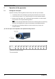
6.2.2 Align pyrometer
The pyrometer is equipped with an LED pilot light for accurate alignment of the sensor with
the object to be measured. Align the pyrometer with the object to be measured as follows:
1. Switch on the supply voltage to the pyrometer.
2. Allow a starting time of approx. 5 minutes for thermo-stabilization. Than the pyrometer
has stabilised and is ready to work with the given accuracy.
3. Switch on the pilot light by pressing the push button at the rear side. Make sure that
there is nothing in the path of rays.
Note:
In order to avoid measuring errors, the area of the pilot light must not be larger
than the object to be measured.
4. If you have a pyrometer with vario optic, adjust the necessary measuring distance (see
page
18).
Note:
The macro-optics cannot be adjusted.
The pyrometer is thus aligned and ready for the temperature measurement.