
Manual


Technical Description
10 KLEIBER 740
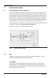
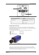
4.1.2 Operating and display elements
The controls and indicators are located on the rear side of the device. For the meaning of
individual elements refer to legend
Fig. 5, for operation of the pyrometer see section 7.
Fig. 5 Operating and display elements
Operating and display element Meaning
1 Push button for pilot light switch on/ off the pilot light
(optional through lens sighting)
2 Potentiometer [emissivity] adjustment of emissivity from 0.1 … 1
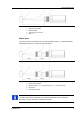
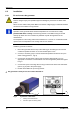
4.1.3 Connections and interfaces
The 5-pole plug to connect the instrument is at the rear side of the unit (see Fig. 66). The
contacts of the 5-pole plug are arranged as follows:
Plug pin Meaning
1 Supply voltage +24 V (DC or AC)
2 Supply voltage 0 V (DC or AC)
3 ground output
4 Analogue output [0 (4) … 20] mA
5 empty