MANUAL IMPAC Pyrometer IGA 6/23 Advanced
Confidential Information The material contained herein consists of information that is the property of LumaSense Technologies and intended solely for use by the purchaser of the equipment described in this manual. All specifications are subject to change without notice. Changes are made periodically to the information in this publication, and these changes will be incorporated in new editions.
Contents 1 General Information...................................................................................................... 5 1.1 Information about the user manual..................................................................... 5 1.1.1 Legend ................................................................................................................. 5 1.1.2 Terminology ........................................................................................................ 5 1.2 Safety ..
.2 4.3 4.4 4.5 4.6 4.7 4.8 4.9 4.10 4.11 4.12 4.13 5 Software InfraWin ....................................................................................................... 29 5.1 5.2 5.3 5.4 5.5 5.6 5.7 5.8 5.9 5.10 5.11 6 Temperature Display ........................................................................................... 23 Emissivity ε .......................................................................................................... 23 Transmittance t.............................
1 General Information 1.1 Information about the user manual Congratulations on choosing the high quality and highly efficient IMPAC IGA 6/23 Advanced pyrometer. This manual provides important information about the instrument and can be used as a work of reference for installing, operating, and maintaining your IGA 6/23 Advanced pyrometer. It is important that you carefully read the information contained in this manual and follow all safety procedures before you install or operate the instrument.
incomplete or incorrect. LumaSense Technologies reserves the right to revise this document and to make changes from time to time in the content hereof without obligation to notify any person or persons of such revisions or changes. All instruments from LumaSense Technologies have a regionally effective warranty period. Please check our website at http://info.lumasenseinc.com/warranty for up-to-date warranty information.
Technical Support can be contacted by telephone or email: Santa Clara, California · Telephone: +1 408 727 1600 or +1 800 631 0176 · Email: support@lumasenseinc.com Frankfurt, Germany · Telephone: +49 (0) 69 97373 0 · Email: support@lumasenseinc.com Erstein, France · Telephone +33 (0)3 88 98 98 01 · Email support@lumasenseinc.com 1.
To ensure consistent document formatting, this page was intentionally left blank.
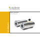
2 Introduction 2.1 Appropriate use 2.2 Scope of delivery The IMPAC IGA 6/23 is a short wave infrared temperature measuring device with digital signal processing. It is used for non-contact temperature measurements on metals, ceramics, graphite, etc. with a temperature range between 50 and 1800 °C. Pyrometer, PC adjustment, and evaluation software InfraWin, works certificate, and operating instructions.
Optics Sighting: Optics: Distance Ratio: Environment Protection Class: Operating Position: Ambient Temperature: Built-in laser aiming light (max. power level < 1 mW, λ = 630 to 680 nm, CDRH class II) or through-lens sighting Manually focusable from rear cover measuring distance a = 210 to 5000 mm MB 10: approx. 50 : 1 MB 13: approx. 100 : 1 MB 18: approx.
Note: The calibration / adjustment of the instruments was carried out in accordance with VDI/VDE directive “Temperature measurement in industry, Radiation thermometry, Calibration of radiation thermometers”, VDI/VDE 3511, Part 4.4. For additional details on this directive, see http://info.lumasenseinc.com/calibration or order the directive from “Beuth Verlag GmbH” in D-10772 Berlin, Germany. 2.4 Dimensions IGA 6/23 Advanced with the view finder IGA 6/23 Advanced with laser sighting 2.
Warning: If selected, the IGA 6/23 Advanced laser light option is a Class 2 and emits laser light. To minimize the risk of eye injury, do not look directly into the beam, and do not point the laser beam of the pilot light into the eyes of another person. 2.6 Accessories (optional) Numerous accessories guarantee easy installation of the pyrometer. The following overview shows a selection of suitable accessories.
Ceremaic The flange system is a modular mounting system to fix the pyrometer on furnaces, vacuum sighting tube 600 x 24, closed chambers, etc. It can consist of e.g. mounting support, tube support withPyrometer air purge and flange and an open or IGA 6/23 Advanced closed ceramic sighting tube.
To ensure consistent document formatting, this page was intentionally left blank.
3 Controls and Installation 3.1 Electrical Installation The IGA 6/23 Advanced is powered by a voltage of 24 V DC ± 25% (ripple < 50 mV). It is important to ensure correct polarity when connecting the device to the power supply. To meet the electromagnetic requirements (EMV), a shielded connecting cable must be used. LumaSense offers connecting cables, which are not part of the standard scope of delivery. The shield of the connecting cable has to be connected only on the pyrometer’s side.
Pin K A L B H J G F C D E M Color white brown green yellow Function +24 V DC power supply 0 V DC power supply + IAusg. analog output – IAusg. analog output Targeting light activate / deactivate via gray external switch (bridged with K) External clearing of max.
Terminator Pyrometer 1 e.g. Address 00 Pyrometer 2 e.g. Address 01 Pyrometer 32 e.g. Address 31 RS485 Bus System 3.1.4 Connection of Additional Units For temperature indication of the pyrometer, LumaSense offers pure indicators (series DA 4000). LumaSense also offers indicators with features to change pyrometer parameters (DA 6000 and DA 6000-N) as well as a fast digital PID controller PI 6000.
3.2 Sighting The IGA 6/23 Advanced can be purchased with Through-Lens Sighting (viewfinder) or with a Laser Targeting Light. These sighting options allow you to easily align the pyrometer to the measuring object. 3.2.1 Viewfinder The IGA 6/23 Advanced can be equipped with a viewfinder which offers through-lens sighting. The viewfinder is true-sided and parallax-free. A circle marks the position of the measuring spot, but not the exact spot size.
Never look directly into the laser beam. The beam and spot can be watched safely from side. Also, make sure that the beam will not be reflected into eyes of people by mirrors or shiny surfaces. The laser targeting light can be switched on and off by pressing the button of the rear cover of the housing. Push button for Laser Targeting Light Note: The laser warning signs on the pyrometer should be easily viewable at all times, even after it has been installed.
Aperture D for all temperature ranges is 13 to 15 mm with the aperture being the effective diameter of the lens. This is dependent on the optical setting. The largest value applies to a very small measuring distance, while the minimum value applies to the largest measuring distance. Measuring Distance a [mm] 210 300 500 800 1300 2000 5000 Spot Diameter M [mm] MB 10 4.2 6 10 16 26 40 100 Spot Diameter M [mm] MB 13 2.1 3 5 8 13 20 50 Spot Diameter M [mm] MB 18 0.6 0.9 1.5 2.3 3.7 5.
The LED Distance Indicator Light (labeled mm) will turn red and the approximate focused measuring distance in mm will automatically be shown on the Digital Display for a few seconds after making an adjustment using the Focus Adjustment Set Screw. Note: Turning the focus adjustment screw counterclockwise will shorten the measuring distance. Turning the focus adjustment screw clockwise will lengthen the measuring distance.
To ensure consistent document formatting, this page was intentionally left blank.
4 Settings / parameter descriptions The pyrometer is equipped with a wide range of settings for optimal adaptation to the required measuring condition and to measure the temperature correctly. All settings can be read and set only in the pyrometer parameters window of the software InfraWin. Adjusting the settings at the instrument is not possible (detailed description of the software see Chapter 5, Software InfraWin). Selecting the pyrometer parameters window shows the current settings of the pyrometer.
Measuring object “Black body furnace“ Extruded Aluminum Brass Brass oxidized (tarnished) Copper Copper, oxidized Inconel Inconel, oxidized Oxidized Iron Steel rolling scale Emissivity [%] (at 2.3 µm) 100 13 18 65 to 70 5 70 to 80 30 85 85 to 90 80 to 88 Measuring object Steel, molten Nickel Titanium, non-oxidized Titanium, oxidized Molybdenum Molybdenum, oxidized Black Carbon Graphite Stoneware, glazed Porcelain rough Emissivity [%] (at 2.
approximately 0.5 ms. The response time can be extended to 1 ms; 3 ms; 5 ms; 10 ms; 50 ms; 250 ms;1 s; 3 s; 10 s. Note: Settings for Response Time t90 min, 1 ms; 3 ms; 5 ms; 10 ms; 50 ms; 250 ms; 1 s; 3 s; 10 s 4.6 Clear Peak Memory (tCLEAR) The integrated maximum value storage is activated when the parameter tclear is set to something other than “OFF” or “HOLD”. If the maximum value storage is switched on, the highest last temperature value will always be displayed and stored.
4.6.2 Clear Time Settings The following settings are available through the InfraWin software or by using the UPP data format commands. OFF When set to OFF, the maximum value storage is switched off and all new temperature values are measured but not stored. 10 ms…25,0 s If the clear time is set between 10 ms and 25.0 s, the maximum value is held in double storage mode. After the entered time, the value will be cleared alternately from one of the storages, while the value of the other storage is shown.
4.9 Device Address When connecting several pyrometers to one serial interface with RS485, it is necessary for each instrument to have its own device address for communication purposes. First, it is necessary to connect each instrument separately to give it an address. After that, all instruments can be connected and addressed individually. Settings: 00 . ..
4.13 Ambient Temperature Compensation Settings: The compensation of the ambient temperature can be set for temperatures auto within the basic measuring range. This compensation is only used for very 00 °C (32 °F) few special applications. The standard setting of this parameter is “auto", .. . because the temperature of the air around the pyrometer is normally the 70 °C (158 °F) ambient temperature of the measured object. Should the measured object be placed in an area with a higher wall temperature (e.g.
5 Software InfraWin The operating and analyzing InfraWin software is included with delivery of the pyrometer. In addition to allowing you to make parameter adjustments, the InfraWin software also provides temperature indication, data logging, and measurement analysis features. This section gives an overview about the functions of the software. It also provides a description of the individual icons found in the program's help menu.
5.4 Basic settings All preset values for the device can be displayed and modified, if necessary under the Devices/Parameters window. Changing an existing pyrometer setting can be accomplished by typing a value in an input box or by selecting a preset value from the list field. Choose the correct settings for your application from the displayed options. This window contains the parameter settings described in Chapter 4, Parameters. 5.4.1 Open/Save 5.4.2 1 measur… 5.4.3 Print 5.4.4 Close 5.4.
In the lower part of the window, the connection with the preset baud rate can be checked. Here the command was sent 100 times with 19200 baud. It has taken 1.100 seconds without transmission errors. Emi: AutoFind: If the true temperature of the measured object is known, you can calculate the emissivity of the measured object using the Emi: AutoFind function: A measured temperature is displayed with the current set emissivity (in this example 100%) (here: 116 °C).
The Scaling Trend button allows you to scale temperature trend view. Note: The measuring values of “measurement online trend” are automatically saved as "standard.i12". Should you need to edit the data later, you need to save the file as another .i12-file because old values are over-written when a new measurement is taken. Files from older program versions (.i10-files) can be opened and saved as .i12. 5.
Note: The last reading is saved in the standard.i12 file and automatically appears in this form upon opening Listing or Trend output. Selecting file open with another file, the previous file will be overwritten and replaced by the standard.i12 file. 5.9 PC sampling rate (time interval between two measurements) This function sets a time interval. After each interval, one measured value is stored on the PC. Longer time intervals will result in creating smaller stored file sizes.
To ensure consistent document formatting, this page was intentionally left blank.
6 Maintenance 6.1 Cleaning the front window Since the device does not contain parts that require regular maintenance, the only regular maintenance required is periodic inspection of the front window for build-up of foreign particiles. If allowed to build up, the particles can influence the energy received by the instrument. The IGA 6/23 Advanced window is not water soluable and can be cleaned with standard lens tissue dampened with a commercially available glasses or camera lens cleaning solution.
To ensure consistent document formatting, this page was intentionally left blank.
7 Data format UPP (Universal Pyrometer Protocol) Software commands can be exchanged directly with the pyrometer through an interface using suitable communication software or by using the “Test” function located in the “Pyrometer Parameters” window of the InfraWin software package.
Description Command Parameters Response time t90 AAezX X=0 to 9 0=min 1=1 ms 4=10 ms 7=1 s Dynamic exposure time AAdmX X=0 to 9 0 = off, 1 = min, 9 = max Temp display °C or °F AAfhX Output: Device address AAgaXX XX=(00 to 97) 00 to 97=regular device addresses 99=global address with response Internal temperature (read) AAgt Answer: DDD 3 decimal digits (000 to 098 °C or 032 to 210 °F) gt=current temp. tm=maximum temp.
Description Command Parameters Read Parameters Aapa Answer: 15 decimal digits DD............. : Emissivity (see em) ..D............ : Response time (see ez) ...D........... : Clear peak memory (see lz) ....D.......... : Analog output (see as) .....DD........ : Internal temperature (see gt) .......DD...... : Device address (see ga) .........D..... : Baud rate (see br ) ..........
To ensure consistent document formatting, this page was intentionally left blank.
8 Reference Numbers 8.1 Reference numbers instrument Temperature Range With Laser Targeting With Viewfinder 50 to 1000 °C (MB 10) 3 914 210 3 914 220 75 to 1300 °C (MB 13) 3 914 250 3 914 260 150 to 1800 °C (MB 18) 3 914 290 3 914 300 Ordering note: A connection cable is not included in scope of delivery and has to be ordered separately. 8.
3 852 550 Power supply NG 2D for DIN rail mounting; 85 to 265 V AC Þ 24 V DC, 600 mA with two settable limit switches 3 890 640 DA 4000-N: LED-digital display to be built into the switchboard, 230 V AC 3 891 210 DA 4000-N: LED-digital display to be built into the switchboard, 115 V AC 3 890 650 DA 4000: like DA 4000-N, but additionally with 2 limit switches, 230 V AC 3 891 220 DA 4000: like DA 4000-N, but additionally with 2 limit switches, 115 V AC 3 890 570 DA 6000-N digital display to allow ad
9 Troubleshooting Symptom No analog output even if the display shows a temperature above lower range limit Temperature reading differs between builtin display and external instrumentation Temperature readings are too low Probable Cause Comments Reversed leads to IGA 6/23 Advanced Reversed leads to other instruments in the current loop Open circuit in lines connecting all instruments in current loop Total burden higher than 500 Ohms Insufficient supply voltage (See wiring diagram) Pyrometer output settin
Symptom Temperature readings are too high Probable Cause Faulty IGA 6/23 Advanced Electrical noise in lead wires caused by intense magnetic fields and/or improper selection of interconnecting cable and/or cable run in same conduit as AC power lines Lens or window clouding up Noisy readings (fast fluctuations) Improper grounding of cable shield and/or IGA 6/23 Advanced housing (or cooling jacket) IGA 6/23 Advanced mounting not secure Target moves more than 95% out of field of view.
Index 1 1 measure… 30 A Accesories 12 Air Purge 12 Analog Output 26 Aperture 20 Appropriate use 9 B Basic settings 30 Baud Rate 27 C Calibration 35 Laboratory 35 On-Site 35 Cleaning the front window 35 Clear Peak Memory 25 Clear Time Settings 26 Close 30 Connecting the pyrometer to a PC 16, 29 Connection cable 9 Connection of Additional Units 17 Connection to RS485 16 Cooling Jacket 12 D Data format UPP 37 Device Address 27 Device Settings Clear Peak Memory tclear 25 Dimensions 11 Disposal 7 Double Stor
Pyrometer Internal Temperature 27 Pyrometer parameters 23 W Warranty 5 R Reference numbers Accessories 41 Instrument 41 Reference Numbers 41 Repair 6, 7 Response Time 24 RS485 16 S Safety 5 Scaling Trend button 32 Scope of delivery 9 Service Request 6 Settings / parameter descriptions 23 Sighting 18 Single Storage Mode 25 Software InfraWin 29 Spot size calculator 33 Spot Sizes 19, 20 Spot sizes for non-focused distances 20 Storage 13 Storage Modes 25 Sub Range 26 Support 6 T Technical Data 9 Temperature