USER MANUAL LumaSpection™ Model BoilerSpection IM
Confidential Information The material contained herein consists of information that is the property of LumaSense Technologies and intended solely for use by the purchaser of the equipment described in this manual. All specifications are subject to change without notice. Changes are made periodically to the information in this publication, and these changes will be incorporated in new editions.
Contents 1 General ............................................................................................................................... 5 1.1 1.2 1.3 1.4 1.5 1.6 1.7 1.8 1.9 2 Introduction ....................................................................................................................... 9 2.1 2.2 2.3 2.4 2.5 3 Using the Main Battery Backpack ......................................................................... 14 Using the Onboard Display ............................
5.1 5.2 5.3 6 Troubleshooting .............................................................................................................. 27 6.1 6.2 6.3 6.4 6.5 6.6 7 Recommended BoilerSpection Maintenance Schedule ...................................... 25 5.1.1 Inspection and Test ................................................................................................25 5.1.2 Preventive Maintenance ........................................................................................
1 General 1.1 Information about the user manual This manual provides important information that can be used as a work of reference for installing, operating, and maintaining your LumaSense BoilerSpection system. It is important that you carefully read the information contained in this manual and follow all safety procedures before you install or operate the system. To avoid handling errors, keep this manual in a location where it will be readily accessible. 1.
the operation of an authorized radio station, by another intentional or unintentional radiator, by industrial, scientific, and medical (ISM) equipment, or by an incidental radiator. The operator of a radio frequency device shall be required to cease operating the device upon notification by a Commission representative that the device is causing harmful interference. Operation shall not resume until the condition causing the harmful interference has been corrected. 1.
Return the instrument upon receipt of the RMA number, transportation prepaid. Clearly indicate the assigned RMA number on the shipping package exterior. Refer to Section 1.8, Shipments to LumaSense for Repair, for shipping instructions. Technical Support can be contacted by telephone or email: Santa Clara, California Telephone (408) 727-1600 or 1-800-631-0176 Email support@lumasenseinc.com Frankfurt, Germany Telephone +49 69 97373 0 Email support@lumasenseinc.
To ensure consistent document formatting, this page was intentionally left blank BoilerSpection IM Manual General 8
2 Introduction The LumaSense BoilerSpection-IM camera is an advanced, easy-to-use mobile imaging solution for furnaces and boilers. The camera operates at an infrared wavelength tuned to provide a clear image inside industrial furnaces.
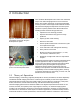
emission from the surface of a material appear as variations of light and shade, or different colors. With our software, the user of the system can store and manipulate the images for analysis. The LumaSense BoilerSpection system uses a specific wavelength of infrared for imaging that enables the system to see through flames and hot combustion gas inside a boiler or furnace. This allows for clear views of boiler walls, tubes and the buildup of slag through the flames during normal and continuous operation.
2.3.1 BoilerSpection Camera and Lens Assembly Inside the rugged BoilerSpection-IM enclosure is an exceptionally precise 320 x 240 focal-plane array microbolometer camera that provides unmatched infrared imaging clarity for uncooled detectors. The camera includes interchangeable borescope optics that are filtered at 3.9 µm wavelength enabling the imager to clearly view through the combustion gas and flames.
2.5 System Specifications Infrared Imaging Camera Image Resolution 320 x 240 pixels Wavelength ~ 3.9 µm narrow band pass filter Detector Type Uncooled VOx Microbolometer Camera weight < 20 lbs Display(s) On Board & Wireless Recording DVR to SD memory card Power Battery (over 24-hour life) Lens Lens Diameter Outer diameter of lens system is 1.
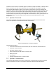
3 BoilerSpection-IM Assembly BoilerSpection-IM is an innovative tool helping today’s plant personnel cope with ever increasing emissions, fuel flexibility, and increased efficiency expectations. BoilerSpection-IM includes state-of the-art optics, an infrared camera, and easy-to-use accessories designed for use in industrial furnace environments include wireless video capture and convenient battery operation. 1. Adjustable radiation shield 2. Interchangeable lens 3. Air fittings for lens cooling/purge 4.
3.1 Using the Main Battery Backpack The main battery backpack is used to power the infrared camera and the video transmitter inside of the camera enclosure for up 20 hours. The backpack is intended to give you the freedom to inspect numerous ports throughout the plant. To Charge the Battery Align the connector on the flex cord to the connector on the charger. A red light will turn on during charging. After charging is complete and the green LED turns on, disconnect the cord from the charger.
1. Turn the ¼-20 socket head cap screws counter clockwise to remove them from the front plate. The lens shroud, lens tube, and air fittings come off as one piece. 2. Align second lens with the threaded holes and insert the three ¼-20 socket head cap screws. 3. Turn them clockwise to tighten. The images below show the process from a side view: 3.
3.6 Installing the Handle If your system was ordered in a storage case, the handle will be installed. If your system was ordered in a travel case, then the handle needs to be screwed clockwise into the base of the camera. To remove the handle, turn it counter-clockwise. Caution: Gloves should be worn when holding the camera in a furnace per the local plant’s safety regulations.
4 BoilerSpection-IM Operation 4.1 Using the On-Board Display An onboard display is attached to a flexible arm allowing you to adjust the position of the display during use. The display has an integrated digital video recording (DVR) to save images and video to a micro-SD memory card. The flexible arm allows you to position the display to either the left or right side of the camera. Power ON/OFF Power Indicator USB Socket Video Output SD Card Socket Power Supply Socket OK Up Menu Down Reset Mount 4.1.
2. Press the OK button to start recording. 1. Press the OK button again to stop recording. To Capture a Photo 1. During operation, press to switch to photo mode. 2. Press OK to capture photo. To Playback a Video/Photo 1. During operation, press 2. Press or to display: to select folder, then press OK to select. 3. For Videos, press BoilerSpection IM Manual or to select folder, then press OK to play.
4. To pause, press OK when the video is playing. Press again to resume. 5. Press to fast forward during playing status. 6. Press to rewind during playing status. 7. Press to stop or exit. 8. For Photos, press or To Delete a Video/Photo 1. During operation, press to select picture, then press OK to display. Press OK again to exit. to display: 2. Press or to select folder, then press OK. 3. Press or to select file, then press and hold 4. Press or to select YES, then press OK to delete file.
4. Press or to select video type. 5. Press OK to confirm and exit. To Change Language Settings 1. During operation, press and hold for 1-2 seconds to enter settings mode. 2. Press or to select System Setting, then press OK. 3. Press or to select Language, then press the OK button. 4. Press or to select suitable language. 5. Press OK to confirm and exit. To Change Date/Time Settings 1. During operation, press and hold for 1-2 seconds to enter settings mode. 2.
Note: The camera wirelessly transmits the video signal on Channel 4. If you have problems receiving an image, check that the display is set to receive on Channel 4. Refer to the troubleshooting section of this manual for additional details. 1. Control Port 2. Power Key 3. HOLD Key 4. REC Key 5. A/V Out 6. A/V In 7. DC In 8. USB Port 4.2.1 9. SD Card Slot 10. RESET 11. Photo Capture Key 12. IR Sensor 13. Volume Down 14. Volume Up 15. 5-Way Navigation Key 16. STOP/ESC Key 17. SET UP Key 18.
1. Plug the supplied DC 5V power adapter to an AC wall outlet and then connect the other end of the power cord to the DC IN socket on the side of the display. The red Charge indicator LED will illuminate while the battery is charging. 2. Once the red Charge indicator LED has turned off, disconnect the display from the DC 5V power adapter. The display is now fully charged and ready to use. 4.2.3 Setting up the Receiver 1. To receive the same video output, the channel should be set at CH4.
4.2.4 Operating the Display To Set Video Storage Options 1. Press and hold the Power button C to turn on the unit. 2. On the main menu, scroll down and select Settings. 3. Scroll to Page 3 of 7 and select Storage Options. 4. Select the preferred option: HDD or SD. To Record Video 1. Press and hold the Power button C to turn on the unit. 2. With the receiver turned on and channel set correctly, press the Record button E to start recording. 3.
To ensure consistent document formatting, this page was intentionally left blank BoilerSpection IM Manual BoilerSpection-IM Operation 24
5 Maintenance The BoilerSpection™ system is designed to operate continuously in harsh environments, but filter replacement and other maintenance measures need to be implemented as described in this section to avoid preventable wear or damage to the system. 5.1 Recommended BoilerSpection Maintenance Schedule 5.1.
Item Description LumaSense Part Number 4 Additional or Spare Lens, 18" (46 cm), wide 75° HFOV 812-0046-61 5 Additional or Spare Lens, 24" (61 cm) straight, standard 50° HFOV 812-0046-22 6 Additional or Spare Lens, 24" (61 cm) straight, wide 75° HFOV 812-0046-62 7 8 Additional or Spare Lens, 24" (61 cm) angled 45° tip, standard 50° HFOV Additional or Spare Lens, 24" (61 cm) angled 90° lens tip, standard 50° HFOV 812-0046-51 812-0046-53 9 Replacement Air Filter 90-2350 10 Replacement Radiat
6 Troubleshooting 6.1 Lens Symptom Poor image – miss slag buildup Probable Cause Corrective Action Lens surface contamination due to dust/dirt in the boiler environment Clean lens with q-tip or install air purge Lens surface contamination during installation/maintenance Clean lens Image offset caused by excessive heat Install air cooling Focus change caused by excessive heat Excessive heat causes lens component to become opaque Loss of image Contact LumaSense (refer to section 1.
6.3 Enclosure Symptom Overheating, internal dust, image quality loss Failure to focus 6.
6.6 Air Filtration System Symptom Loss of air pressure Probable Cause Corrective Action Clogged filter Check that filters are not clogged up and follow proper maintenance schedule (see section 5) Leaky connections Check that the connections are secure and tighten as necessary Leaky/damaged hose Contact LumaSense (refer to section 1.
To ensure consistent document formatting, this page was intentionally left blank.
7 System Diagrams 7.1 BoilerSpection IM System Diagrams Figure 6: BoilerSpection IM Model Diagram Section 7.1.1 – IM Borescope Assembly Drawing o Figure 7: IM Dimensions with Borescope Lens Assembly Section 7.1.2 – IM Interchangeable Lens Drawings o Figure 8: Drawing of straight interchangeable lens Section 7.1.3 – IM Air Filtration System Mechanical Drawings o Figure 9: IM Air Filtration System Components Section 7.1.
7.1.
7.1.
7.1.
7.1.
Figure 11: IM Storage Case Drawing 2 BoilerSpection IM Manual System Diagrams 36
Figure 12: IM Travel Case Drawing 1 BoilerSpection IM Manual System Diagrams 37
Figure 13: IM Travel Case Drawing 2 BoilerSpection IM Manual System Diagrams 38
Figure 14: IM Air Filtration Case Drawing 1 BoilerSpection IM Manual System Diagrams 39
Figure 15: IM Air Filtration Case Drawing 2 BoilerSpection IM Manual System Diagrams 40
To ensure consistent document formatting, this page was intentionally left blank.
Index 1 12VDC power input 13 A Adjusting Focus 23 Air Filters and Hoses 15 Air Filtration Case 39, 40 Air Filtration System 34 Air fittings for lens cooling 13 Auxiliary BNC Video Output Connector 23 B BNC video output 13 BoilerSpection Camera and Lens Assembly 11 BoilerSpection IM Assembly 10 BoilerSpection System 13 BoilerSpection-IM Operation 17 Borescope Lens 14 Installing 14 C Camera Specifications 12 Capturing Photos 17 D Date/Time Settings 20 Delete a Video/Photo 19 Disposal / Decommissioning 7
System Components 10 System Diagrams 31 System Overview 10 System Settings 19 Date/Time 20 Language 20 Time Stamp 20 Video 19 System Specifications 12 T Theory of Operation 9 Training 5 Transferring Recorded Images and Videos to PC 23 Travel Case 37, 38 Troubleshooting 27 Camera 27 Enclosure & Air Purge 28 Lens 27 U Unpacking and Inspection 6 V Video System Settings 19 BoilerSpection IM Manual Index 43