
Installation Guide


3. Position and secure all wires away from all other electrical components.
4. Close access door, ensure mylar barrier is pushed inside the xture and tighten
door screw (25-30 in-lbs).
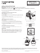
PHOTOCONTROL (SHIPPED ATTACHED TO FIXTURE)
TOOLS REQUIRED: Flathead screwdriver.
1. Remove NEMA photocontrol, loosen two athead screws enough to allow rotation
of the receptacle.
2. Insert screwdriver into center slot and rotate receptacle until indicator arrow points
north or desired direction. Tighten screws.
3. Insert the photocontrol (or shorting cap) into receptacle and twist into locked
position.
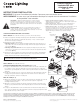
SMALL REFRACTOR (SOLD SEPARATELY)
TOOL REQUIRED: 1/4" Socket or athead screw driver.
1. Insert provided 8-32 x 1/2" thread forming screws into mounting holes.
Place 1/8" o-rings over screw threads to hold screws within refractor. (FIG. 8)
2. Center refractor to luminaire housing and align refractor thru-holes to die-cast
housing mounting holes. (FIG. 9)
3. Tighten the two screws into holes provided in die-cast housings (approximately
7-10 in-lbs.).
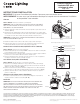
ANSI/NEMA REFRACTOR (SOLD SEPARATELY)
1. Place latches over latch hooks in housing and snap latches down to secure
refractor to housing. (FIG. 10)
MAINTENANCE
NOTE: A REGULAR MAINTENANCE SCHEDULE SHOULD BE FOLLOWED TO
RETAIN OPTIMAL LIGHT OUTPUT AND THERMAL PERFORMANCE. OPTICAL
LENSCLEANINGSHOULDBEPERFORMEDWITHACLEANDRYCLOTHTO
REMOVEANYDUSTOROTHERCONTAMINANTS.ADDITIONALCLEANING
CAN BE PERFORMED WITH NON-ABRASIVE CLEANSER.
Lumark Caretaker
TM
LED Area Luminaire
Sheet 2 of 2
IMI-802
© 2013 Eaton. All Rights Reserved. Publication No. ADH131711 November 2013
www.cooperlighting.com
Eaton’s Cooper Lighting Business
1121 Highway 74 South. Peachtree City, GA 30269
These instructions do not claim to cover all details or variations in the equipment, procedure, or process described, nor to provide directions for meeting every possible
contingency during installation, operation or maintenance. When additional information is desired to satisfy a problem not covered sufciently for user’s purpose, please
contact your nearest representative. NOTE: Specications and dimensions subject to change without notice.
INSTALLATION INSTRUCTIONS
IMPORTANT: Read before installing xture. Retain for future reference.
WARNING: Make certain power is OFF before starting installation or attempting any maintenance.
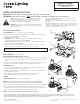
FIG. 7 - Wiring Diagram No Terminal Block
FIG. 6
Supply Neutral
Supply Line (Hot)
Supply Ground
White Neutral
WIre Nuts (Provided)
Mylar
Barrier
Black (Line)
Green (Ground)
FIG. 8
O-Ring
8-32 Threaded
Forming Screw
FIG. 10
Refractor
FIG. 11
Latches Over
Casting Hooks