
Installation Guide


WALL/POLE MOUNT BRACKET
TOOL REQUIRED: 7/16" Socket wrench, drill, 3/16" drill bit.
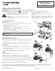
1. Remove wall/pole mount bracket from xture and set aside two 5/16"-18" xture
mounting bolts. Discard pipe-clamp bracket.
2. Determine mounting surface.
•Wall Mount: Place bracket (wall/sq pole mount) face against mounting
surface, with bracket arrow pointing up. (FIG. 1)
•Wood Pole Mount: Place bracket (wood pole mount) face against pole with
bracket arrow pointing up. (FIG. 2)
3. Make sure bracket is level. Drill Ø3/16" pilot holes. Drive four 1/4" x 2" long lag
bolts (provided) where indicated. Tighten bolts to approx. 6-8 ft-lbs.
NOTE: DO NOT USE “FIXTURE” MOUNTING HOLES TO FASTEN BRACKET TO
MOUNTING SURFACE.
LUMINAIRE INSTALLATION
TOOLS REQUIRED: 1/2" Socket wrench.
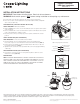
WALL/POLE MOUNT BRACKET (FIG. 3 and 4)
1. With supply wires pulled through either 1/2" conduit hole 6" to 8", slide xture down
over bracket and ensure support tab is correctly positioned inside the housing wall
cavity.
2. Using 1/2" socket, drive the two pipe-clamp mounting bolts up through universal
bracket and into luminaires threaded bolt holes. Tighten to 14-16 ft-lbs.
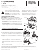
PIPE ARM (FIG. 5)
1. Use a 1/2" socket to remove the two 5/16"-18 pipe-clamp mounting bolts and
remove and discard wall/pole mount bracket.
2. Re-attach pipe-arm bracket leaving enough space to allow mounting arm to slide
onto desired leveling step.
3. With supply wires pulled through mounting pipe 6" to 8", tighten the two
pipe-clamp mounting bolts using 1/2" socket to 14-16 ft-lbs.
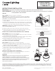
WIRING
TOOLS REQUIRED: Philips or athead screwdriver.
NOTE: ALL WIRING TO BE DONE IN ACCORDANCE WITH THE NATIONAL
ELECTRICAL CODE AND APPLICABLE LOCAL GODES AND ORDINANCES.
1. Open xture using screw driver and allow access door to hang from hinge. (FIG. 6)
2. Pull supply wires into xture housing and connect ground service wire to green
factory installed wire. Connect line service lead (hot wire) to black factory installed
wire. Connect neutral service wire to white factory installed wire.
NOTE: SEE WIRING DIAGRAM FOR ADDITIONAL DETAILS (FIG. 7)
Lumark Caretaker
TM
LED Area Luminaire
Sheet 1 of 2
IMI-802
© 2013 Eaton. All Rights Reserved. Publication No. ADH131711 November 2013
www.cooperlighting.com
Eaton’s Cooper Lighting Business
1121 Highway 74 South. Peachtree City, GA 30269
These instructions do not claim to cover all details or variations in the equipment, procedure, or process described, nor to provide directions for meeting every possible
contingency during installation, operation or maintenance. When additional information is desired to satisfy a problem not covered sufciently for user’s purpose, please
contact your nearest representative. NOTE: Specications and dimensions subject to change without notice.
SAFETY: This xture must be wired in accordance with the National
Electrical Code and applicable local codes and ordinances. Proper
grounding is required to insure personal safety. Carefully observe
grounding procedure under installation section.
WARNING: Make certain power is OFF before starting installation or
attempting any maintenance. Risk of re/electric shock. If not qualied,
consult an electrician.
•RISKOFELECTRICSHOCK—Disconnectpoweratfuseorcircuit
breaker before installing or servicing.
•RISKOFBURN—Disconnectpowerandallowxturetocoolbefore
servicing.
•RISKOFPERSONALINJURY—Fixturemaybecomedamagedand/or
unstable if not installed properly. Tighten all xture components to their
recommended torque values. Do not lift pole into place by securing
lifting device to lighting xture or mounting arm.
INSTALLATION INSTRUCTIONS
IMPORTANT: Read before installing xture. Retain for future reference.
WARNING: Make certain power is OFF before starting installation or attempting any maintenance.
FIG. 1
FIG. 2
Fixture
Support Ta b
(4) 1/4" x 2" Long
Lag Bolts
(4) 1/4" x 2" Long
Lag Bolts
1/2" Conduit
Hole
FIG. 3
Pipe Clamp
(2) Mounting
Bolts
(2) Mounting
Bolts
(2) Mounting
Bolts
FIG. 4
FIG. 5