
Service Manual User guide

12.3
Model 644E-42/944E-42 Rev. 6/04
Index
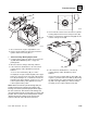
Enclosed Cab (Optional)
Components .................................4.24
Enclosed Cab Components
Heater/Defroster System ............ 4.24
Windshield Wiper Assembly ....... 4.24
Engine Air-Intake
Heater Indicator ..........................9.182
Engine Block Heater ..................... 9.241
Engine Block Heater Removal ........ 7.21
Engine Coolant High Temperature
Sender ........................................9.237
Engine Coolant Temperature
Gauge......................................... 9.182
Engine Cooling System..................... 7.8
Radiator Pressure Cap ................. 7.8
Radiator, Transmission Oil Cooler
and Hydraulic Oil Cooler
Replacement............................ 7.14
Thermostat Replacement .............7.8
Engine Exhaust System..................7.30
Installation................................... 7.31
Removal...................................... 7.30
Engine Function
Indicator Lights ........................... 9.179
Engine Low Oil Pressure
Sender ........................................9.235
Engine Replacement
Disassembly, Inspection
and Service.............................. 7.40
Installation................................... 7.41
Removal...................................... 7.32
Engine Serial Number....................... 7.7
Engine Start Circuit
Starter....................................... 9.164
Starter Circuit Checks............... 9.164
Starting Circuit .......................... 9.163
Engine Tachometer....................... 9.182
Engine: Cummins 4BT3.9
Cooling System............................. 7.8
Electrical System ........................ 7.23
Exhaust System.......................... 7.30
Fuel System................................ 7.23
Introduction...................................7.3
Replacement............................... 7.32
Safety Information......................... 7.5
Serial Number...............................7.7
Specifications and Maintenance
Information................................. 7.7
Standard Practices ....................... 7.7
Storage .......................................7.49
Troubleshooting.......................... 7.50
F
Fluids, Lubricants and Capacities
Axles (Differential Housings).......2.23
Drive Shaft Splines......................2.26
Engine.........................................2.24
General Anti-Corrosion................2.26
Hydraulic System ........................2.24
Lubrication Points
(Grease Fittings).......................2.24
Paint ............................................2.27
Thread Locking Compound.........2.27
Transfer Case..............................2.25
Transmission...............................2.25
Wheel Ends.................................2.23
Front Roller Gap Check.................11.19
Front Roller Shimming...................11.20
Front Upstop Wear Pad Check......11.14
Front Upstop Wear Pad
Gap Check ..................................11.14
Front Upstop Wear Pad
Replacement ...............................11.16
Front Upstop Wear Pad
Shimming ....................................11.15
Fuel Filter Replacement ..................7.27
Fuel Injectors...................................7.28
Fuel Level Gauge ..........................9.182
Fuel Level Indicator .......................9.242
Fuel Level Sender .........................9.242
Fuel Lift Pump Removal ..................7.26
Fuel Lift Pump Testing.....................7.26
Fuel System.....................................7.23
After Fuel System Service...........7.29
Diesel Fuel ..................................7.24
Fuel Filter ....................................7.27
Fuel Injectors...............................7.28
Fuel Level Sender and
Gauge.......................................7.25
Fuel Lift Pump Testing ................7.26
Fuel Tank ....................................7.24
Venting Air from the Fuel
System .....................................7.27
Fuses and Relays
Circuit Protection - Fuses............9.21
Locations.....................................9.22
Replacement ...............................9.25
G
Gauges..........................................9.182
General Information, Specifications and
Maintenance
After Service Startup and
Checks .....................................2.30
Bearings......................................2.29
Cleaning......................................2.27
Component Terminology...............2.3
Fluids, Lubricants and
Capacities ................................2.23
Hoses and Tubes........................2.28
Introduction ...................................2.4
Metric Conversion Factors............2.7
Pressure Testing and
Adjustment...............................2.29
Replacement...............................2.28
Specifications..............................2.10
Torques.........................................2.5
Ground Strap Locations ..................9.16
H
Hazard/Emergency Information
Decals and/or Decal Plates............. 1.7
Heater ...........................................9.206
Hoses and Tubes
Inspection....................................2.28
Installation................................... 2.28
Hoses, Tube Lines, Fittings, Etc.
Replacement.................................8.8
Replacement Considerations........8.8
Hourmeter ..........................9.182, 9.244
Hydraulic Circuits and Troubleshooting
Attachment Tilt (Down) and
Slave Cylinder Circuit
(Dual Joystick) ......................... 8.98
Attachment Tilt (Down) and
Slave Cylinder Circuit
(Single Joystick).....................8.100
Attachment Tilt (Up) and Slave
Cylinder Circuit
(Dual Joystick) .......................8.102
Attachment Tilt (Up) and Slave
Cylinder Circuit
(Single Joystick).....................8.104
Attachment Tilt and Slave
Circuit Description
(Dual Joystick) .......................8.153
Attachment Tilt and Slave
Circuit Description
(Single Joystick).....................8.154
Auxiliary Hydraulic Circuit
(Female Coupler Pressurized -
Dual Joystick)..............8.134, 8.136
Auxiliary Hydraulic Circuit
(Female Coupler Pressurized -
Single Joystick)...........8.138, 8.140
Auxiliary Hydraulic Circuit
(Male Coupler Pressurized -
Dual Joystick)..............8.126, 8.128
Auxiliary Hydraulic Circuit
(Male Coupler Pressurized -
Single Joystick)...........8.130, 8.132