
Service Manual User guide

Electrical System
9.22
Model 644E-42/944E-42 Rev. 6/04
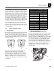
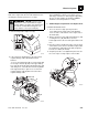
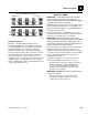
9.7.2 Fuse and Relay Locations
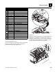
The fuse and relay block is mounted under the lower right
side of the operators side console (1). To gain access,
remove the cover plate (2) from the right side console.
Remove the plastic cover (3) from the fuse and relay
block.
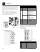
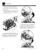
Refer to the relay and fuse location charts for the
locations of fuses and relays within the fuse block.
When reassembling the cover to the side console, torque
the capscrews to 7-8 lb-ft (9,5-10,6 Nm).
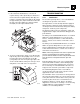
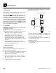
a. Fuse Block Relay Locations
b. Flasher
The flasher (4) for the optional roadlights is located in the
upper right hand corner of the fuse block. Pull the flasher
straight out to replace.
c. Fuse Locations
OU0670
1
2
3
1
2
3
4
5
6
7
8
9
10
11
12
13
14
15
16
17
18
19
20
21
22
23
24
25
26
27
28
E10E5
E4 E9
E3 E8
E2 E7
E1 E6
MU33802
4
No. Volt Circuit Controlled
E1
12 Volt Transmission Control
E2
12 Volt Ignition
E3
12 Volt Neutral Start
E4
12 Volt Back-Up Alarm
E5
12 Volt
Stability Brake
(644E-42, SN 20118 & Before,
SN 0160002519 thru
0160003877)
(944E-42, SN 20123 & Before,
SN 0160002514 thru
0160003881)
–
Open
(644E-42,
SN 0160003878 & After)
(944E-42,
SN 0160003882 & After)
E6
12 Volt Stability Lock
E7
12 Volt Boom Proximity
E8
12 Volt Light Power (Option)
E9
12 Volt Cab Power (Option)
E10
– Open
No. Amp Circuit Protected
1
40 Amp Open Cab Vehicle Main
2
15 Amp Ignition Control
3
15 Amp Transmission
4
20 Amp Fuel Solenoid
5
20 Amp Ignition Power
6
10 Amp Back-Up Alarm/Horn
1
2
3
4
5
6
7
8
9
10
11
12
13
14
15
16
17
18
19
20
21
22
23
24
25
26
27
28
E10E5
E4 E9
E3 E8
E2 E7
E1 E6
MU33902