WARNING: Improper operation of this vehicle can cause injury or death. Only trained and authorized operators should operate this vehicle. Before starting the engine, do the following: 1. Read this owner/operators manual. 2. Read all the safety decals on the vehicle. 3. Clear the area of other persons. Learn and practice safe use of vehicle controls in a safe, clear area before you operate this vehicle on a worksite.
Table of Contents Introduction The Manual....................................2 Replacement Parts ........................2 Reports ..........................................2 Disclaimer......................................3 Safety Practices Hazard Classification System........3 Accident Prevention Tags..............5 New or Additional Operators .........5 Instructional Symbols ....................6 Instructional Symbols (cont’d) .......7 Hazard Symbols ............................8 Avoidance Symbols .....
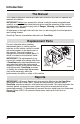
Introduction Introduction The Manual This Owners/Operators Manual provides the information you need to operate and maintain this vehicle. IMPORTANT! Before you operate this vehicle, read this manual completely and carefully so you will understand the instructions and the operation of the controls and equipment. You must comply with all Danger, Warning, and Caution notices; they are for your benefit.
Safety Practices Disclaimer OmniQuip reserves the right to make changes on and to add improvements upon its products at any time without public notice or obligation. OmniQuip also reserves the right to discontinue manufacturing any product at its discretion at any time. NOTICE: Under OSHA rules, it is the responsibility of the employer to provide operator training. Successful completion and certification of Safety Training for Rough Terrain Forklifts is required.
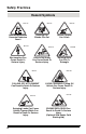
Safety Practices Signal Word A signal word is a distinctive word located on hazard decals and used throughout this manual that alerts the viewer to the existence of and relative degree of the hazard. DANGER: The signal word “DANGER” indicates an imminently hazardous situation which, if not avoided, will result in death or serious personal injury. WARNING: The signal word “WARNING” indicates a potentially hazardous situation which, if not avoided, could result in death or serious personal injury.
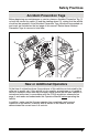
Safety Practices Accident Prevention Tags Before beginning any maintenance or service, place an Accident Prevention Tag (1) on both the starter key switch (2) and the steering wheel (3), stating that the vehicle should not be operated. Actual Accident Prevention Tags, which can be punched out and used, are included as the last page of this manual. Retain these Accident Prevention Tags for reuse at a later date.
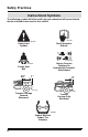
Safety Practices Instructional Symbols The following symbol definitions will help you understand all hazard related decals and load charts used on this vehicle. OH2100 OP0330 Read Operator’s Manual Safety Alert Symbol OH3100 Always Connect Couplers On Hydraulically Powered Attachments OH2090 Fasten Seat Belt 80" 1" 0" OU1570 OU1580 Transfer Carriage Forward Movement Transfer Carriage Fully Retracted OS0900 Always Maintain Proper Tire Pressure 6 Model 644E Rev.
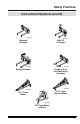
Safety Practices Instructional Symbols (cont’d) OU1620 OU1630 Standard Carriages Side Tilt Carriages OU1610 OU1640 Single or Dual Fork Positioning Carriages Swing Carriages OU1590 OU1600 10 Ft. Truss Boom w/Winch 10 Ft. Truss Boom OU1560 3 Ft. Truss Boom w/Winch Model 644E Rev.
Safety Practices Hazard Symbols OH2110 OH2120 OH2130 - Lead Acid Batteries Generate Explosive Gases Rotating Fan Blades Can Cut OH2150 Electrocution Can Cause Death Or Serious Injury OH2140 Vehicle Roll Away Can Cause Death Or Serious Injury OH2161 FALLING OFF ATTACHMENT Can Result In Death Or Serious Injury OH3110 Swinging Loads Can Cause Vehicle Tipover Which Can Result In Death Or Serious Injury 8 Vehicle Tipover Can Crush OH2300 Rotating Belts Can Cut Or Entangle OH3160 AVOID CRUSHING
Safety Practices Avoidance Symbols OH2320 OH2330 Keep Lit Cigarettes Away Keep Flames and Ignition Sources Away OH2280 Do Not Raise Boom While On A Slope OH2270 Do Not Travel With Boom Raised OH2240 Do Not Travel With Personnel In Work Platform OH2250 Keep Clear Of Power Lines OH2310 Keep Away From Rotating Fan Blades Model 644E Rev.
Safety Practices Avoidance Symbols (cont’d) OH2260 OH2290 Engage Parking Brake Maintain Proper Air Pressure In Tire OH2170 OH2230 Use Only Compliant Work Platforms To Raise Or Lower Personnel Carry No Riders OH2220 DO NOT JUMP OU1460 DO NOT Use Ether Or Other High Energy Starting Aids. Engine Equipped With Grid Heating System.
Safety Practices Avoidance Symbols (cont’d) OU1530 OU1540 Keep Truss Boom Horizontal When Using Winch Avoid Rope Damage. DO NOT Tilt Truss Boom DOWN When Using Winch OU1550 Avoid Rope Damage. DO NOT Tilt Truss Boom UP When Using Winch OU1520 Stop Operation At this Point OU1510 Prohibition Symbol. DO NOT Operate Model 644E Rev.
Safety Practices Personal Considerations 1. Seat Belt Always fasten the seat belt before starting the engine. 2. Clothing and Safety Gear DO NOT wear loose clothing or jewelry that can get caught on controls or moving parts. Wear protective clothing and personal safety gear issued or called for by job conditions. 3.
Safety Practices DO NOT use ether or any other high energy starting aids during cold starting. An engine explosion can result in death or serious personal injury. ENGINE EXPLOSION can DO NOT use Ether or other result in death or serious high energy starting aids. personal injury. Engine equipped with grid heating system. D.
Safety Practices Battery Charging WARNING: DO NOT charge a frozen battery, it may explode and cause serious injury. Let the battery thaw out before putting on a battery charger. Under normal conditions, the engine alternator will have no problem keeping the battery or batteries charged. The only condition in which the battery may cause a problem is when the battery or batteries have been completely discharged for an extended period of time.
Safety Practices 5. Moving Parts Hazard DO NOT place limbs near moving parts. Severing of any body part can result. Turn off engine and wait until fan and belts stop moving before servicing. MOVING PARTS can cut. Keep clear of fan and belts while engine is running. MOVING PARTS can entangle. OT0810 6. Lowering Boom or Falling Load Hazard DO NOT get under a raised boom unless it is blocked up safely.
Safety Practices 2. Clearances Look out for and avoid other personnel, machinery and vehicles in the area. Use a spotter if you do not have a clear view of conditions that affect clearances. Travel with the boom fully retracted and lowered as far as possible while still maintaining enough ground clearance for conditions. Always check boom clearances carefully before driving underneath door openings, bridges, etc. Always check for power lines when raising the boom. Beware of overhead wires.
Safety Practices 6. Elevating Personnel Use only a compliant work platform meeting the ASME B56.6 standards for lifting and lowering personnel. NEVER transport personnel in a work platform for even the shortest distance. Death or serious personal injury can occur if these rules are not obeyed. Riders can fall and be crushed or run over. Avoid accidents. For other specific precautions, See “Elevating Personnel” on page 89.
Safety Practices 8. Tip Over Hazard VEHICLE TIPOVER can result in death or serious injury. DANGER DO NOT travel with the boom raised. MAINTAIN proper tire pressure at all times. DO NOT raise boom while on a slope unless load is level. OS0086 Traveling with the boom raised is dangerous and can cause tipover. Keep the boom as low as possible. Travel with extreme caution and at the slowest possible speed. Keep the vehicle under control at all times.
Safety Practices 10. Tire Pressure VEHICLE TIPOVER can result in death or serious injury. DANGER DO NOT travel with the boom raised. DO NOT raise boom while on a slope unless load is level. MAINTAIN proper tire pressure at all times. OS0085 MAINTAIN proper tire pressures at all times. An underpressurized tire(s) adversely affects vehicle stability. If proper tire pressures are not maintained, this vehicle can tip over.
Safety Practices 13. Falling Load Hazard DO NOT exceed the total rated load capacity of the specific type fork being used. Each fork is stamped with a maximum load capacity. If the capacity is exceeded, forks may break. See “Fork Rating” on page 72. DO NOT downshift at a high ground speed. Sudden slowing can cause the load to drop off the forks. 14. Ventilation Sparks from the electrical system and the engine exhaust can cause an explosion.
Safety Practices 3 5 1 WARNING AVOID CRUSHING, falling off vehicle can cause death or serious injury 1. Read operator's manual before operating. SAFETY INSTRUCTIONS 2. Fasten seat belt. 3. Allow no riders. 4. Use a compliant work platform to lift or lower personnel. 4110361 7 15 20 10 1/2 F E °F 176 RPM X 100 104 25 5 80 °C 248 120 D 30 r/min 0000000 Allow no riders 4 DANGER AVOID CRUSHING if vehicle tips. Jumping can result in death or serious injury.
Safety Practices WARNING FALLING OFF ATTACHMENT, can result in death or serious injury. 3 6 Ft 200cm Lift or lower personnel only in a compliant work platform. DO NOT TRAVEL with personnel in a work platform. 190cm 180cm 170cm 160cm 5 Ft 150cm 140cm 130cm 4 Ft 120cm 110cm 100cm 3 Ft 90cm 2 70cm 1 Ft Ft 80cm 60cm 50cm 40cm 30cm 20cm 10cm 0 4110356 5 4110389 B A 4 6 MOVING PARTS can cut.
Operation Operation Pre-Operation Inspection 1. Check seat belt for damage. Check for frayed or cut seat belt webbing, damaged buckles or loose mounting brackets. Make any necessary repairs before operating the vehicle. 2. Check all four tires and rims for damage. Check for proper tire pressure, add air if required. Observe the condition of each tire looking specifically for punctures, cracks, cuts, gouges, bulges or any other damage. Check the condition of each rim for bent flanges or any other damage.
Operation Operators Seat Adjustments Enter the cab using the hand holds. The operator’s seat can be adjusted as follows: Fore and Aft Adjustment (all styles of seat) Pull the handle (1) under the front of the seat (2) to the left and move the seat forward and backward. Release the handle to lock the seat in the desired position. Depending on the style of seat, this handle may be on the right side or the left side of the seat.
Operation Seat Belt WARNING: Serious bodily injury or death may result from failure to wear the seat belt installed on this vehicle. The seat belt is a critical component of the Operator’s Protective Structure, and is provided for the operators protection in case of vehicle upset. The seat belt MUST be worn whenever this vehicle is operated. IMPORTANT! Inspect the seat belt every time it is used, looking for cut or worn webbing, or any defect in the latch assembly.
Operation Operator Controls Accelerator Pedal Pressing down the accelerator pedal (1) increases engine speed and the speed of the hydraulic system. The pedal is spring-loaded to return to idle speed. Service Brake Pedal Pressing down the brake pedal (2) decreases the speed of the vehicle by applying the service brakes located in the axles. In the event of engine power loss, the service brake pedal can also be used for braking.
Operation Ignition Switch The ignition switch is located on the lower right side of the front dash. Using the ignition switch key (5), the key may be turned clockwise from the OFF (6) position to the RUN (7) and START (8) positions. The START position is spring-loaded to return to the RUN position and must be manually held in place for starting. OFF position (6) — The entire electrical system is shut down. RUN position (7) — All controls and indicators are operable.
Operation 1. Four Wheel Steering Mode WARNING: NEVER use the Four Wheel Steering Mode when traveling at high speed. Rapid turning in this mode can cause tipover. Use only the Front Wheel Steering Mode at higher speeds and slow the vehicle when turning. The front wheels will steer in the direction that the steering wheel is turned; the rear wheels will steer in the opposite direction.
Operation 3. Crab Steering Mode WARNING: NEVER use the Crab Steering Mode when travelling at high speed. Rapid turning in this mode can cause tipover. Use only the Front Wheel Steering Mode at higher speeds and slow the vehicle when turning. All wheels will steer in the same direction that the steering wheel is turned. This steering mode allows the operator to move the vehicle “sideways” toward the landing point of a load.
Operation Parking Brake Switch The Parking Brake Switch (1) is located on the left side of the front dash and has two positions: P P ENGAGED .................... toggle switch downward DISENGAGED ...................toggle switch upward OS1323 OS0121 The Parking Brake Switch must be ENGAGED to permit engine starting. A red LED, on the parking brake switch, will indicate the brake is ENGAGED. The parking brake engaged light (2) will illuminate on the front dash panel any time the parking brake is engaged.
Operation Transmission Disconnect Switch The Transmission Disconnect Switch (3) is located on the left side of the front dash and has two positions: • Push the TOP of the rocker switch in to DEACTIVATE the transmission disconnect function. OH2591 • Push the BOTTOM of the rocker switch in to ACTIVATE the transmission disconnect function.
Operation Travel Select Lever The Travel Select Lever (1) has three positions to select direction of travel: F = FORWARD (2) .............................. all the way UP N = NEUTRAL DETENT (3) ................ CENTER position R = REVERSE (4) ............................... all the way DOWN OS0340 1 1 2 F 1st 2nd 3rd 4th N 3 5 R OU0400 4 Starting Travel 1. Enter the operator cab, fasten the seat belt, start the engine, apply the service brake pedal and disengage the parking brake switch. 2.
Operation Changing Travel Direction 1. Stop the vehicle by applying the service brakes. 2. Grasp the travel select lever (1), pull it toward the steering wheel, then move the lever up or down in the opposite direction; (R) REVERSE (4) or (F) FORWARD (2). When the Travel Select Lever is shifted to REVERSE, the back-up alarm will automatically sound. NOTE: The Travel Select Lever must be in the (N) NEUTRAL DETENT (3) position to permit engine starting.
Operation Stopping Travel 1. Apply the service brake pedal and downshift the vehicle to a lower gear if necessary to slow the vehicle until it comes to a complete stop. 2. Move the travel select lever (1) to the (N) NEUTRAL DETENT position and engage the parking brake switch. F 2 N R 1 OU0390 Maximum Fork Sweep (During Travel) CAUTION: Allow for adequate clearance between the attachment and rear counterweight and other objects when turning.
Operation Joystick Operation This vehicle is equipped with three separate joysticks. • The front joystick (5) controls attachment tilt and PlaceAce™ transfer carriage operation. The button (6) on the front joystick controls the auxiliary hydraulic function. • The middle joystick (7) controls boom lift/lower and extend/retract functions. • The rear joystick (8) is a single axis joystick with a lift to shift lock ring detent and controls the frame sway to the left and right.
Operation Front Joystick (Attachment Tilt & Transfer Carriage) The front joystick (1) controls the attachment tilt and the PlaceAce™ transfer carriage operation. The joystick can be moved from the center position into any of these quadrants. The joystick will return to the center position when released. The button on the top of the joystick controls the auxiliary hydraulics function. Refer to “Auxiliary Hydraulic Control” on page 40 for a detailed explanation. Attachment Tilt Up (2) ....................
Operation Middle Joystick (Boom Lift/Lower & Boom Extend/Retract) The middle joystick (6) controls the boom lift/lower and boom extend/retract functions. The joystick can be moved from the center position into any of these quadrants. The joystick will return to the center position when released. Boom Lift (7) ................................ move handle backward Boom Lower (8) ........................... move handle forward Boom Extend (9) .........................
Operation Frame Sway Joystick The frame sway joystick (1) is equipped with a lock ring (2) to prevent unintentional operation of the frame sway control. Lift up and hold the lock ring while moving the handle to the left or right. When frame sway is complete, center the handle and lower the lock ring to lock the handle in the center position. Frame Sway Right (3)....... LIFT lock ring and move handle to the RIGHT Frame Sway Left (4) .........
Operation Leveling The Vehicle When placing a load while on a slope, use the frame sway control. Keep the vehicle level. The operator should observe the frame level indicator (5) to assure that the vehicle is level at all times. The frame sway is capable of tilting the vehicle 12° in either direction. 5 OS0232 DANGER: Use of the frame sway control with the boom raised above horizontal can cause tipover resulting in death or serious personal injury.
Operation Auxiliary Hydraulic Control The auxiliary hydraulic control is used to control the functions of an optional attachment that is mounted to the vehicle and requires a hydraulic supply for operation. Some of the optional attachments that require auxiliary hydraulics are: Side Tilt Carriage, Swing Carriage, 3 ft Truss Boom w/Winch, 10 ft Truss Boom w/Winch, Single Fork Positioning Carriage, Dual Fork Positioning Carriage and Auger.
Operation 5 6 OU0090 While holding the button down and moving the joystick to the right (3) will provide hydraulic system pressure through the female disconnect coupling for the auxiliary attachment. Hydraulic fluid will return to the tank through the male disconnect coupling. While holding the button down and moving the joystick to the left (4) will provide hydraulic system pressure through the male disconnect coupling for the auxiliary attachment.
Operation Joystick Operation (Single Joystick Option) The single joystick option is an assembly containing a single joystick (1) to control boom functions, auxiliary hydraulics, attachment tilt and the PlaceAce™ transfer carriage operation. The frame sway is controlled by a separate frame sway joystick (2) which is located behind the single joystick assembly.
Operation Boom Lift/Lower and Extend/Retract (Default Mode) Front button (3), not depressed, operates the following boom functions. The joystick can be moved from the center position into any of these quadrants. The joystick will return to the center position when released. Boom Lift (5) ................................ move handle backward Boom Lower (6) ........................... move handle forward Boom Extend (7) ......................... move handle to the right Boom Retract (8) ......................
Operation Transfer Carriage Extend/Retract and Auxiliary Hydraulic Male Pressurized/ Female Pressurized (Secondary Mode) Front button (1) depressed and held against the joystick handle operates the following transfer carriage and auxiliary hydraulic functions. The joystick can be moved from the center position into any of these quadrants. The joystick will return to the center position when released. Transfer Carriage Extend (2)............................ move handle forward Transfer Carriage Retract (3) .
Operation 6 7 OU0090 While holding the button in and moving the joystick to the right (4) will provide hydraulic system pressure through the female disconnect coupling for the auxiliary attachment. Hydraulic fluid will return to the tank through the male disconnect coupling. While holding the button in and moving the joystick to the left (5) will provide hydraulic system pressure through the male disconnect coupling for the auxiliary attachment.
Operation Attachment Tilt (Thumb Control) Operates in Default Mode or Secondary Mode The thumb control (1), on the topside of the joystick, controls the attachment tilt function and is not affected by the button (2) on the front of the joystick. With your thumb, move the thumb control BACKWARD for attachment tilt UP (3). Move the thumb control FORWARD for attachment tilt DOWN (4). The thumb control will return to the center position when released. Attachment Tilt UP (3) .................
Operation Leveling The Vehicle When placing a load while on a slope, use the frame sway control. Keep the vehicle level. The operator should observe the frame level indicator (9) to assure that the vehicle is level at all times. The frame sway is capable of tilting the vehicle 12° in either direction. 9 OS0232 DANGER: Use of the frame sway control with the boom raised above horizontal can cause tipover resulting in death or serious personal injury.
Operation Front Dash Panel The front dash panel (1) provides the operator with important information. It is “user friendly” and only provides the operator with the information needed at any given time. Front Dash Panel Light Test 4 5 3 1 15 20 10 1/2 °F 176 RPM X 100 F E 104 25 5 80 °C 248 120 D 30 r/min 0000000 2 OU0010 To test the front dash panel lights; turn the ignition switch to the RUN position, ALL the lights (13 total) will come ON for three seconds as a test function.
Operation Function Indicator Lights There are four “hidden” function indicator lights in the front dash panel that illuminate only when a specific function has been activated. They are: Parking Brake Indicator (2) This light illuminates any time the parking brake is applied and the ignition switch is in the RUN position.
Operation Warning Indicator Lights There are seven additional “hidden” indicator lights in the front dash panel that will illuminate during critical circumstances. All seven warning indicator lights demand immediate attention and vehicle servicing. In many cases, the vehicle should be shut down AS SOON AS PRACTICAL to prevent serious mechanical failure.
Operation Alternator Charging Warning Indicator (4) This light illuminates to indicate a weak or improperly working charging system or the batteries are dead. Service the engine alternator or batteries. OH2560 Engine Air Filter Restriction Warning Indicator (5) This light illuminates when a restricted engine air filter is detected. If the light is ON, service the air filter(s).
Operation Low Brake Pressure Warning Indicator (1) This light is located on the lower right side of the front dash panel. OM1600 The light will come ON and the buzzer sounds when service brake hydraulic system pressure drops below the safe operating level. Under normal conditions, the light and buzzer will go out quickly after engine start. If the light or buzzer does not go out or comes ON during vehicle operation, shut off engine immediately, investigate, and repair before operating.
Operation Gauges and Indicators Fuel Level Gauge (2) Make sure the vehicle is level to ensure an accurate fuel level OH24701 reading. The fuel gauge located on the left side of the front dash panel, indicates the amount of fuel in the fuel tank. Refuel before the fuel gauge reaches the “E” to prevent running out of fuel. Capacity of the fuel tank is 50.2 gallons (190 liters) total capacity with a usable capacity of 45 gallons (171 liters).
Operation Optional Indicator Lights There are two additional “hidden” indicator lights in the front dash panel that will illuminate only when the vehicle is equipped with the optional road light package. High Beam Indicator (1) Whenever the headlights are on “high” beam this light will illuminate and remain ON until the headlights are switched to “low” beam.
Operation Optional Features Worklights (Front, Rear & Boom) The worklights are activated with a single rocker OH2570 switch (3) located in the upper switch bank on the right side. There are three positions - OFF, Front Worklights and Front and Rear Worklights. The lights only work when the ignition switch is in the RUN position. • Push the TOP of the rocker switch in to turn all the worklights OFF. OH2591 • To turn the front worklights ON, position the rocker switch to the CENTER position.
Operation Parking Lights, Headlights & High/Low Beam Switch OS1900 These lights will only work when the ignition switch is in the RUN position. Use the turn signal switch (1) to control the high/low beam headlights and to turn ON the parking lights and headlights. Turn the twist grip end (2) of the turn signal switch counterclockwise to the first position (3) to turn the parking lights ON. Turn the twist grip to the second position (4) to turn the headlights and parking lights ON.
Operation Directional Signals The directional signals are OS1910 ACTIVATED from the lever (6) on the right side of the steering wheel and will only work when the ignition switch is in the RUN position. To activate the left turn signal (7); RAISE the lever. To activate the right turn signal (8); LOWER the lever. To deactivate either directional signal, the lever must be manually returned to the CENTER position. The lever will not cancel automatically after a turn. 6 7 8 Model 644E Rev.
Operation Emergency Flashers The emergency flashers are activated by a single rocker switch (1) located in the upper bank of switches on the right side of the dash. OS1920 • To DEACTIVATE the emergency flashers, push the TOP of the rocker switch IN. OH2591 • To ACTIVATE the emergency flashers, push the BOTTOM of the rocker switch IN.
Operation Door Latches (Closed Cab Only) There are two door latches for the lower door. The outside latch (3) is a key lockable pull-to-release type. The inside latch (4) is a pull-to-release latch. Door Window Latch (Closed Cab Only) The door window (5) can be swung open by releasing the window from inside the cab. Release the window from the door with the window latch handle (6). Pivot the handle out of the way and swing the window open.
Operation Rear Window Latches (Closed Cab Only) The rear window (1) can be partially opened and secured in place with the rear window latch. To open the window, grab the latch handle (2), PULL UP and then push the window OUTWARD. To close and secure the window, pull the latch handle UP and then INWARD. NOTE: In an emergency situation, the operator can exit through the rear window opening by removing the latch pin (3) on the window latch. The window is then free to swing open. 3 1 1. 2. 3.
Operation 9 4 8 5 6 7 OU1010 Windshield Installation IMPORTANT! Be sure the windshield retainer plate is secured in place after installing the windshield back into the cab. Never operate the vehicle with the windshield in place and the retainer plate missing. 1. With the seal bulb on the windshield toward the cab, place the top of the windshield under the upper retainer (9). Push the windshield up as far as possible. 2. Place the bottom of the windshield (4) into the windshield opening in the cab.
Operation Front Windshield Wiper (Closed Cab Only) OS19301 This three position rocker switch (1) is located in the lower bank of switches on the right side of the dash. This single rocker switch controls the speed of the front windshield wiper. • Push the TOP of the rocker switch in to turn the front wiper OFF. OH2591 • Place the rocker switch in the MIDDLE position to operate the wiper at LOW speed. OH2601 • Push the BOTTOM of the rocker switch in to operate the wiper at HIGH speed.
Operation Windshield Washer Control (Closed Cab Only) This rocker switch (2) is spring loaded to return to the OFF position when released. The switch is located in the lower bank of switches on the right side of the dash. OS19401 • Release the switch to deactivate the washer control. OH2591 • Press and hold the BOTTOM of the rocker switch in to activate the windshield washer. The rocker switch is spring loaded and will return to the OFF position when released.
Operation Rear Window Wiper (Closed Cab Only) The rear window wiper rocker switch (1) is located on the motor housing of the rear wiper. OM1530 The switch has two positions: wiper ON (2) and wiper OFF (3). 1 2 3 OU0170 Cab Heater/Air Conditioning Controls (Closed Cab Only) OS1960 OS1950 The cab heater and air conditioning controls (4) are located in the lower bank of switches on the right side of the dash.
Operation To heat the cab: • turn A/C switch (6) to the OFF position, OS1950 • turn temperature control knob (7) to far right position (RED = HOT), • direct desired air flow by adjusting vent louvers, • turn fan control (5) to position “3” (8) to assure rapid warm-up. To defrost the cab: • turn temperature control knob (7) to the far right position (RED = HOT), OA1390 • direct desired air flow by adjusting vent louvers, • turn fan control (5) to position “3” (8) to assure rapid defrost.
Operation Carriages Quick Attach This vehicle is equipped with a quick attach system for easy attachment changing. Attachment Removal Be sure you are performing this procedure on level ground. 1. Come to a complete stop, place the travel select lever in the (N) NEUTRAL DETENT position and engage the parking brake switch. 2. Extend the boom approximately 10 feet (3 meters) and tilt the carriage backward. 3. Exit the vehicle using both hand holds. 4.
Operation Attachment Reconnect Be sure you are performing this procedure on level ground. 1. Position the vehicle directly behind the attachment to be mounted. 2. Tilt the quick attach backward. 3. Extend the boom approximately 10 feet (3 meters) and drive the vehicle forward until the attachment pivot pins are below and between the two hooks on the attachment. 4. Raise the boom until the attachment pivot pins have seated fully in the hooks of the attachment. 5. Tilt the attachment up slightly.
Operation Auxiliary Hydraulic Pressure Release Switch (If so equipped) The Auxiliary Hydraulic Pressure Release Switch (1) is located in the upper bank of switches on the right side of the dash. This switch is used to release pressure in the auxiliary hydraulic system before connecting or disconnecting the Auxiliary Hydraulic Couplings. OS21402 1. Bring the vehicle to a complete stop. 2. Park the vehicle on level ground. 3.
Operation This Page Intentionally Left Blank Model 644E Rev.
Operation Indicators Boom Angle Indicator The boom angle indicator (1) is a bubble type indicator with angular graduations (2) from -20° to +80°. It is located on the left side of the outer boom (3) and is visible from the operators position. Use this indicator to determine the boom angle when reading the capacity chart (see “Using the Capacity Chart” on page 73). 1 3 2 OU0460 Boom Extension Indicator The boom extension indicator is a series of letters (4) that become visible as the boom is extended.
Operation Transfer Carriage Extension Indicator The transfer carriage extension indicator (6) shows the operator the distance the transfer carriage has moved from the fully retracted position. Use this indicator along with the boom extension indicator, boom angle indicator and the load chart booklet supplied with the vehicle to determine safe load placement. 6 OU0540 Rear View Mirrors Three rear view mirrors are provided to aid the operator’s rear visibility.
Operation Fork Rating All approved forks for this vehicle are marked with a maximum load capacity rating. This rating is stamped on the left edge of the fork (1) just below the fork pivot shaft (2). The rating is listed in U.S. pounds and based upon a 24" (610 mm) load center (3).
Operation Using the Capacity Chart The individual capacity charts are located on the dash on the right side of the operator’s compartment. Capacity charts are provided to assist the operator in determining how far in front, how high and at what angle a specific load can be safely handled with this vehicle. IMPORTANT! Always determine whether a load chart is required whenever using an attachment with this telescopic material handler.
Operation To accurately use the capacity chart, the operator must first determine three important things: 1. Weight of the load being lifted. 2. Height of the structure where the load is to be placed. 3. Distance where the load will ultimately be placed in front of the front tires. Reading Capacity Charts Example: (1) 1. The operator has placed the load onto the forks, fully retracted the boom, positioned the vehicle perpendicular to the structure and leveled the vehicle. 2.
Operation Sample Capacity Chart 4110409 Use with OmniQuip approved carriages only. 644E-42 36 32 28 24 20 0" 16 44 12 8 60° 40 4 F D 32 40° C B 28 30° 24 20 16 20° 12 8 10° 4 0 ft. -4 SAFETY INSTRUCTIONS E 50° 36 0 ft. 66° -5° 4 3 0 0 2 0 1 0 0 0l 5 0 0 b 0 0 bl 0 l l b Always connect couplers on hydraulically powered attachments. 1 A 6 0 0 0 l b 0" 24" b ASME B56.6b -1998 29 26 22 18 14 0 ft. 2 48" & 50" OU0681 Model 644E Rev.
Operation Stabil-TRAK System Understanding the Stabil-TRAK™ System The following describes the three basic modes of the patented Stabil-TRAK system. The vehicle may operate in any one of these three modes. OS1970 Free Pivot Mode With the boom below 40° (1), the Stabil-TRAK system is in the FREE PIVOT MODE (2) and the rear axle is allowed to pivot freely. The frame sway control will function normally. Both Stabil-TRAK lights on the front dash panel will be OFF (3).
Operation Locked Mode With the boom above 40° (4) and by activating one or more of the functions (as follows), the Stabil-TRAK system is in the LOCKED MODE (5). The rear axle is locked so it is rigid with the frame. The Stabil-TRAK lock light on the front dash panel will be ON (6). The Stabil-TRAK slow pivot light on the front dash panel will be OFF (7).
Operation Slow Pivot Mode With the boom above 40° (1), the Stabil-TRAK System is now in the SLOW PIVOT MODE (2) when the service brake pedal is not applied and the transmission is in gear. In this mode the rear axle is UNLOCKED and is allowed to pivot but will respond SLOWLY to changes in terrain. The Stabil-TRAK slow pivot light on the front dash panel will be ON (3). The Stabil-TRAK lock light on the front dash panel will be OFF (4).
Operation Stabil-TRAK™ System Test To test the function of the Stabil-TRAK system, read the Stabil-TRAK System Test Instructions on this page and follow Steps 1 through 9 of the Stabil-TRAK System Test Procedures starting on page 80. Stabil-TRAK™ System Test Instructions • Test the Stabil-TRAK system with the vehicle on a level surface. • Remove any attachment from the quick attach before performing the test. • DO NOT extend the boom at any time during the test.
Operation WARNING: DO NOT operate this vehicle unless you are in the seat with the seat belt fastened around you. Death or serious personal injury could result if the belt is not securely fastened. Stabil-TRAK™ System Test Procedures Step 1: a. Place the vehicle on a level surface with 0° sway. b. Have the boom fully retracted and horizontal. c. Place an 8" (203 mm) wood or cement block in front of the front left tire. d. Enter the vehicle. e. Fasten the seat belt. f.
Operation Step 4: a. Use your left foot to fully depress the service brake pedal. b. Move the travel select lever to (R) REVERSE and the range selector to the (1) FIRST gear position. c. Ease your left foot off the service brake pedal, just keeping the StabilTRAK lock light ON (approximately 3/4 pedal travel). d. With your right foot, increase the engine RPM, as necessary, to back the vehicle off the block.
Operation Step 8: a. Depress the service brake pedal fully. b. Disengage the parking brake switch. c. With the range selector in (1) FIRST gear, move the travel select lever to the (R) REVERSE position. d. Release the service brake pedal to deactivate the Stabil-TRAK system. e. The Stabil-TRAK lock light should go OFF and the Stabil-TRAK slow pivot light should come ON. f. The front left tire should return to the ground while the vehicle travels in reverse. g.
Operation Refueling Make sure the vehicle is level to assure an accurate fuel level reading. The fuel tank is capable of holding 45 gallons (171 liters) of diesel fuel. Fuel Types OS0860 The preferred fuel is ASTM #2 diesel fuel with a minimum Cetane rating of 40. #2 diesel fuel gives the best fuel economy and performance under most operating conditions.
Operation Fuel Cap The fuel cap (1) is conveniently located on the left side of the vehicle. The fuel cap meets EPA standards and a fuel cap key (2) must be used to unlock (3) and lock (4) the fuel cap. To unlock and remove the fuel cap: 1. Level the vehicle, ground the attachment, place the travel select lever in the (N) NEUTRAL DETENT position, engage the parking brake switch and turn the ignition switch to the OFF position. Remove the keys from the ignition. 3 4 2 1 OU0480 2.
Operation Normal Starting 1. Enter the cab and adjust the seat for comfortable operation. 2. Adjust the mirrors to obtain the best rear view from the operator’s position. WARNING: DO NOT start the engine unless you are in the seat with the seat belt fastened around you. Death or serious personal injury could result if the belt is not securely fastened. 3. Fasten the seat belt. 4. Make sure the parking brake switch is ENGAGED. 5. Place the travel select lever in the (N) NEUTRAL DETENT position. 6.
Operation Cold Starting The engine is equipped with a 120 volt 750 watt block heater. Block heaters are recommended when temperatures drop below 10° F (-12° C). (Temperature ranges will vary when using different oil weights. Consult the engine manufacturer’s manual for other variables. FOR ENGINES EQUIPPED WITH OPTIONAL COLD STARTING AID WARNING: This diesel engine uses a grid heating system inside the induction manifold. DO NOT use ether or any high energy fuels to assist starting.
Operation Jump Starting WARNING: NEVER jump start the vehicle directly to the starter solenoid. Death or serious personal injury could result from the vehicle lurching forward or backward and running over the person attempting to jump start the vehicle directly to the starter. WARNING: To avoid death or serious personal injury when jump starting with another vehicle, be certain that the two vehicles are not touching. Never jump start the vehicle with a frozen battery as it will explode.
Operation How To Pick, Carry & Place A Load To pick a load, move the forks inward or outward on the fork shaft so that they are aligned with the openings in the pallet. Extend the boom slowly so the forks slide into the openings in the pallet. Raise the boom so that the load is lifted. To carry a load, position the boom so that the load is as low as possible and the travel area is visible to the operator.
Operation Elevating Personnel This vehicle is designed to lift and transport materials and should not be used to elevate personnel except as explained in this section. Only equipment designed and approved for elevating personnel should be used. If the vehicle must be used to elevate personnel, use only a compliant work platform. Refer to “Defining Platforms For Elevating Personnel” on page 89 for requirements.
Operation 7. The platform must have a restraining means such as a guardrail or a means of securing personnel such as a body belt or lanyard for each occupant of the platform. 8. The guardrail or similar structure shall have a nominal height to the platform floor of 42" (1066 mm) around the perimeter of the platform and include a midrail.
Operation Preperation and Set-up WARNING: Never allow anyone to alter or modify any part of the work platform. Any modification to the platform which could result in serious personal injury to anyone on the platform. 1. DO NOT alter or modify the work platform in any manner. 2. Make sure that the work platform is securely attached to the quick attach or forks. Follow the platform manufacturer’s instructions. 3.
Operation Elevating Personnel WARNING: Never operate the Attachment Tilt function to tilt the platform forward or rearward when elevating with personnel aboard. Death or serious personal injury could result. DANGER: Never operate this or any equipment in an area in which overhead or underground cables or power sources exist without first requesting that the appropriate power company or utility company de-energize the lines or take other suitable precautions. 1.
Operation Using Other Attachments Numerous attachments, marketed by OmniQuip are available for this vehicle. The capacity charts attached to this vehicles dash are to be used with OmniQuip approved attachments only. Hydraulically powered attachments must only be used on vehicles equipped with auxiliary hydraulics. IMPORTANT! This vehicle is intended for the function of lifting only. This vehicle is not designed to PULL, TOW or DRAG other objects.
Operation The attachments listed below are supplied with their own individual set of capacity charts as shown in the last section of this manual: • 72" Swing Carriage • 10 Foot Truss Boom • 10 Foot Truss Boom w/Winch • 3 Foot Truss Boom w/Winch Hydraulically actuated attachments also have a maximum hydraulic pressure rating.
Operation Shut-Off 1. Bring the vehicle to a complete stop using the service brakes. 2. Park the vehicle on level ground. WARNING: To prevent death or serious personal injury, be certain to lower the boom, engage the parking brake switch, and shut off the engine prior to exiting the vehicle. 3. Place the travel select lever in the (N) NEUTRAL DETENT position and engage the parking brake switch. 4. Lower the boom and ground the attachment. 5.
Emergency Operations Emergency Operations Towing a Disabled Vehicle Towing a disabled vehicle should only be attempted after exhausting all other options. Every effort should be made to repair the vehicle and move it under its own power. Towing the vehicle improperly can result in damage to the vehicle drivetrain. IMPORTANT! In the event the vehicle is disabled and cannot be moved under engine power, the situation must be properly evaluated and dealt with on an individual basis.
Emergency Operations 11. Pressurize the park brake with the pressurizing unit. Pump pressure into the park brake system. DO NOT exceed 650 psi (45 bar). Close the pump needle valve on the pressurizing unit. CAUTION: DO NOT exceed 650 psi (45 bar) when pressurizing the park brake. Applying too much pressure may damage the brake seals. 2 3 1 4 OU0741 12. Watch the pressure gauge on the pressurizing unit to ensure that the pressure in the park brake system does not drop during the towing operation. 13.
Emergency Operations Emergency Boom Lowering This section discusses emergency boom lowering procedures: Part l: In case of loss of engine power or hydraulic pump failure. Part ll: In case of hydraulic line failure. Part l Loss of Engine Power or Hydraulic Pump Failure IMPORTANT! In the event of total loss of engine power or hydraulic pump failure with an elevated load, the situation must be properly evaluated and dealt with on an individual basis.
Emergency Operations In any case of hydraulic line failure, it is critical to correctly identify which hydraulic line has failed. Identify the hydraulic line that has failed and use the table on page 100 to determine which Step to follow to retract and lower the boom.
Emergency Operations NORMAL STEPS HYDRAULIC LINE THAT FAILED BOOM LIFT LINE (LIFT CYLINDER TO BLOCK OR BLOCK TO FRAME BULKHEAD) BOOM LOWER LINE (LIFT CYLINDER TO BLOCK OR BLOCK TO FRAME BULKHEAD) BOOM EXTEND LINE (EXTEND CYLINDER TO BLOCK OR BLOCK TO FRAME BULKHEAD) BOOM RETRACT LINE (EXTEND CYLINDER TO BLOCK OR BLOCK TO FRAME BULKHEAD) FOLLOW THIS STEP IF PARTS ARE AVAILABLE FOLLOW THIS STEP IF PARTS ARE NOT AVAILBLE STEP 1 STEP 2 STEP 1 Refer to STEP 1 STEP 1 STEP 2 STEP 1 Refer to STEP 1 STEP
Emergency Operations 5. Replace the failed hydraulic line with a new part. • Boom Extend Line - Extend Cylinder to Block (1) • Boom Retract Line - Extend Cylinder to Block (2) • Boom Extend Line - Block to Frame Bulkhead (3) • Boom Retract Line - Block to Frame Bulkhead (4) • Boom Lower Line - Lift Cylinder to Block (5) • Boom Lift Line - Lift Cylinder to Block (6) • Boom Lower Line - Block to Frame Bulkhead (7) • Boom Lift Line - Block to Frame Bulkhead (8) 6.
Emergency Operations STEP 2 USE IN CASE OF: BOOM LIFT LINE FAILURE - Lift Cylinder to Block (1) BOOM LIFT LINE FAILURE - Block to Frame Bulkhead (2) BOOM EXTEND LINE FAILURE - Extend Cylinder to Block (3) BOOM EXTEND LINE FAILURE - Block to Frame Bulkhead (4) 1. Clear the area of any unnecessary personnel. 2. Block all four wheels. WARNING: Wear protective clothing and proper eye protection when working with or around hydraulic oil. Wait for hydraulic oil to cool before attempting to repair the failure.
Emergency Operations 3 4 1 2 OU1060 Model 644E Rev.
General Maintenance General Maintenance Introduction This section of the manual contains a maintenance schedule and checklist with references to pertinent procedures and instructions. To prevent problems before they occur, follow the maintenance schedule. NOTE: The Lubrication (1) and Maintenance Chart (2) decals are located inside the engine cover (3). They contain a general maintenance schedule that should be followed to maintain the vehicle in good operating condition.
General Maintenance Maintenance Schedule and Checklist 10 50 LB-F T (N m) 100 250 1000 P 2000 OU0510 Model 644E Rev.
General Maintenance 1. Lubrication Points 50 Lubricate the following grease fittings using Multi-Purpose Grease (MPG) every 50 hours: OS1750 OH2680 NOTE: Shorten the lubrication interval on all lube points when operating in severe conditions or during high cycling operation. 2 2 OU0520 106 Model 644E Rev.
General Maintenance 2. Air Cleaner The front dash panel illuminates an indicator light that will alert the operator when it senses restricted air flow to the engine. This indicates the air filter(s) needs servicing. NEVER operate the vehicle without the air cleaner assembly and both filters in place. A.
General Maintenance 2. Remove the primary element (1). Inspect the element for damage. Damaged elements should never be reused. 4 1 6 2 5 OU0200 3 3. Thoroughly clean the interior of the air filter canister (2) and vacuator valve (3). 4. If replacing the inner element (4) at this time, carefully slide the element out. Always discard this element and replace with a new element. 5. Slide the new primary element over the inner element making sure the sealing edge is flush with the base of the air cleaner.
General Maintenance 3. Optional Closed Cab Air Filters The optional closed cab has two air filters. These filters require periodic maintenance. Recirculation Air Filter Periodically remove and inspect the recirculation air filter (7) located directly behind the seat. Remove the two thumb screws (8) holding the vent cover and filter (7) to the heater assembly housing (9). Gently hand wash with water. A mild detergent may also be used if the filter is saturated with dirt.
General Maintenance 4. Engine Cooling System A. Engine Coolant Level Check (10 Hour Intervals) 1. Level the vehicle, ground the attachment, place the travel select lever in the (N) NEUTRAL DETENT position, engage the parking brake switch and shut off the engine. 10 OH2660 OS0800 2. Unlatch and open the engine cover. 3. Check the coolant level in the overflow bottle (1). When the coolant is hot, the bottle should be 1/2 to 3/4 full. When the coolant is cool, the bottle should be 1/4 to 1/2 full.
General Maintenance B. Drain and Flush Radiator (2000 Hour Intervals) 1. Level the vehicle, ground the attachment, place the travel select lever in the (N) NEUTRAL DETENT position, engage the parking brake switch and shut off the engine. 2000 OH2700 OS0810 WARNING: DO NOT attempt this procedure when the engine is hot. Wait for the engine, muffler and tailpipes to cool down before proceeding. Failure to do so could result in severe burns. 2. Unlatch and open the engine cover.
General Maintenance 4. Locate the petcock (1) on the bottom of the radiator. Place a hose (2) onto the petcock and channel the coolant into a container. Open the petcock and allow the coolant to drain. 5. Flush the radiator with clean water and allow to drain. After radiator is drained, close the petcock and remove the hose. 6. Transfer to used coolant to a properly labeled container and dispose of properly. 2 1 MU1390 7.
General Maintenance 3 5 4 MU13802 9. Fill the radiator completely with a 50/50 mixture of ethylene glycol and water. Replace the radiator cap. Add coolant to the overflow bottle until the bottle is 1/2 to 3/4 full. This “overfilling” will compensate for any air in the cooling system. 10. Clean any dirt and debris from the radiator fins and core. 11. Start the engine and run the vehicle to the normal operating temperature, then shut off the engine. While the engine is cooling, check for leaks. 12.
General Maintenance 5. Engine Oil and Filter Engine Oil Recommendations The use of quality engine oil combined with the appropriate oil and filter change intervals are critical factors in maintaining engine performance and durability. Use 15W40 motor oil that at least meets the manufacturers minimum recommended oil specifications as defined in their operator manual. A. Oil Level Check (10 Hour Intervals) 10 1.
General Maintenance B. Oil and Filter Change (250 Hour Intervals) 1. Operate the engine until warm (approximately 5 minutes). 250 OS0830 OH2710 2. Level the vehicle, ground the attachment, place the travel select lever in the (N) NEUTRAL DETENT position, come to a complete stop, engage the parking brake switch and shut off the engine. 3. Unlatch and open the engine cover. 4. Place a receptacle under the engines oil pan drain petcock (4) or drain plug (6).
General Maintenance 1 OU0310 7. Remove the oil filter (1) and clean the filter sealing surface. 8. Apply a thin coat of clean engine oil to the new filter mating surface. 9. Install the new oil filter and hand tighten. Use an oil filter wrench or strap to tighten the filter down another 1/4 to 1/2 turn. 116 Model 644E Rev.
General Maintenance 10. Turn the oil drain petcock lever (2) clockwise and lock into the CLOSED position or install the drain plug (3) into the oil pan and tighten securely. The petcock lever is spring loaded and will lock in the CLOSED position. 3 2 OU0302 11. Remove the engine oil fill cap (4) and add 15W40 motor oil. (Refer to engine manufacturers manual for recommended oil type for various conditions.) Engine oil capacity with filter change is 10.5 quarts (10 liters). 12. Reinstall oil fill cap (4).
General Maintenance 6. Engine Fuel System A. Drain Water from Fuel Water Separator/Filter (10 Hour Intervals) 10 H 20 OH2660 Unlatch and open the engine cover. OS0851 Loosen the drain cock (1) on the underside of the fuel filter (2) and allow all the water to drain into a container until clear fuel is visible. Dispose of properly. Tighten drain cock after draining. Close and latch engine cover. 3 2 1 OU0270 118 Model 644E Rev.
General Maintenance B. Change Fuel Filter (250 Hour Intervals) 250 OH2710 OS0870 The fuel filter (2) must be changed at shorter intervals with evidence of water or contaminated fuel. 1. Unlatch and open the engine cover. 2. Clean around the fuel filter head (3). 3. Unscrew the fuel filter and dispose of properly. 4. Clean the gasket surface of the filter head and replace the o-ring. 5. Fill the new fuel filter with clean No. 2 diesel fuel. 6. Lubricate the o-ring seal with clean No. 2 diesel fuel. 7.
General Maintenance C. Replace In-line Fuel Strainer 250 (250 Hour Intervals) OH2710 1. Unlatch and open the engine cover. 2. The fuel strainer (1) is located down line from the engines lift pump (2). Loosen the two hose clamps (3) that secure the strainer in place. 3. Remove the old strainer and dispose of properly. 4. Install the new strainer with arrow (4) pointing toward the lift pump. 5. Assemble the hoses to the strainer and tighten the hose clamps. 6.
General Maintenance D. Bleeding Fuel System Air must be vented from the fuel system whenever any component between the fuel tank and the injection pump has been disconnected, or when the system has been emptied or run out of fuel. WARNING: DO NOT bleed the fuel system of a hot engine. Doing so could create a fire hazard. Allow the engine to cool before bleeding the fuel system. IMPORTANT! DO NOT attempt to start the engine until the injection pump has been filled and primed with fuel.
General Maintenance WARNING: KEEP CLEAR of spraying fuel. Fuel can spray when venting high pressure lines. The fuel pressure is sufficient to penetrate the skin and cause serious bodily injury. Wear protective clothing and safety glasses. 4. To vent the high pressure fuel lines (1), loosen one fitting (2) at the injector (3). 5. Turn the ignition switch to the START position and crank the engine for a maximum of 15 seconds or until fuel, free of air, comes out of the injector fitting. 6.
General Maintenance 7. Engine Fan Belt Engine Fan Belt Check (1000 Hour Intervals) 1000 OH2690 1. Level the vehicle, ground the OS08802 attachment, place the travel select lever in the (N) NEUTRAL DETENT position, engage the parking brake switch and shut off the engine. 2. Unlatch and open the engine cover. 3. Inspect the fan belt (4). Replace if cracked or frayed. 4. This engine is equipped with an automatic belt tensioner (5). Inspect the tensioner bearing.
General Maintenance 8. Air Conditioner Compressor Belt (Optional) Air Conditioner Compressor Belt Check (1000 Hour Intervals) 1000 OH2690 1. Level the vehicle, ground the attachment, place the travel select lever in the (N) NEUTRAL DETENT position, engage the parking brake switch and shut off the engine. 2. Unlatch and open the engine cover. 3. Inspect the air conditioner compressor belt (1). Replace if cracked or frayed. 4.
General Maintenance 9. Hydraulic Oil and Filter A. Hydraulic Oil Level Check 10 (10 Hour Intervals) OH2660 OS0660 1. Level the vehicle, place the travel select lever in the (N) NEUTRAL DETENT position and engage the parking brake switch. 2. Lower and retract the boom, level and lower the attachment to the ground, transfer the transfer carriage to the rear position and shut off the engine. 3. Unlatch and open the engine cover. 4. Allow the hydraulic oil to cool. 5.
General Maintenance B. Hydraulic Oil & Filter Change (First 100 Hours - Filter Only) 100 (1000 Hour Intervals - Oil & Filter) OT0840 OU0530 1000 OS0840 OH2690 Change the hydraulic oil filter after the first 100 hours of operation and change the hydraulic oil and filter every 1000 hours of operation thereafter. The hydraulic filter must be changed anytime the hydraulic oil filter restriction warning indicator light on the front dash panel comes ON.
General Maintenance 14 1 5 11 7 6 12 13 8 2 3 9 4 10 OU0330 13. Place a receptacle under the hydraulic reservoir drain plug (10). The receptacle must be large enough to hold 35 gallons (132 liters) of oil. Remove the drain plug and allow the oil to drain into the receptacle. Transfer the oil to a container with a cover and label the container as used oil. Dispose of properly. 14. Re-install the drain plug (10) into the reservoir. Torque the drain plug to 25-40 lb-ft (34-54 Nm) 15.
General Maintenance 10. Transmission Oil and Filter Approved Universal Tractor Fluid JOHN DEERE JDM J20C (HY-GARD) FORD/NEW HOLLAND ESN-M2C134-D (HYDRAULIC OIL 134) MASSEY FERGUSON M-1141 (PERMATRAN lll) CHEVRON CHEVRON 1000 THF A. Transmission Oil Level Check (10 Hour Intervals) 10 1. Level the vehicle, ground the attachOS0890 ment, place the travel select lever in OH2660 the (N) NEUTRAL DETENT position and engage the parking brake switch. 2.
General Maintenance B. Transmission Oil & Filter Change (First 100 Hours) (1000 Hour Intervals) 100 OU0530 1000 OH2690 OS0950 1. Level the vehicle, ground the attachment, place the travel select lever in the (N) NEUTRAL DETENT position, engage the parking brake switch and shut off the engine. 2. Unlatch and open the engine cover. Allow the engine and transmission to cool. 3. Place a receptacle under the transmission drain plug (2).
General Maintenance 5. If your vehicle is equipped with the optional cold staring aid (dual batteries) (4), loosen, do not remove the upper battery tray retainer bolt (1). Swing the upper battery tray out to gain access to the transmission filter. 6. Remove the filter (2) and dispose of properly. Clean the mating surface where the filter mounts. 7. Apply a thin film of clean Universal Tractor Fluid to the new filter gasket. Carefully install a new filter (2). 8.
General Maintenance 11. Transfer Case Oil Approved Universal Tractor Fluid JOHN DEERE JDM J20C (HY-GARD) FORD/NEW HOLLAND ESN-M2C134-D (HYDRAULIC OIL 134) MASSEY FERGUSON M-1141 (PERMATRAN lll) CHEVRON CHEVRON 1000 THF A. Transfer Case Oil Level Check (250 Hour Intervals) 250 OH2710 OU0560 1.
General Maintenance B. Transfer Case Oil Change (First 100 Hour Intervals) and (1000 Hour Intervals) 100 OU0530 OU0550 1000 1. Place the vehicle on level OH2690 ground, ground the attachment, level the vehicle side to side, place the travel select lever in the (N) NEUTRAL DETENT position, engage the park brake switch and shut off the engine. 2. Clean the area around the transfer case oil fill/level plug (1) and the oil drain plug (2). 3. Place a receptacle under the transfer case drain plug. 4.
General Maintenance 12. Axle Oil A. Axle Oil Level Check (250 Hour Intervals) 250 OH2710 OU0610 Approved Universal Tractor Fluid JOHN DEERE JDM J20C (HY-GARD) FORD/NEW HOLLAND ESN-M2C134-D (HYDRAULIC OIL 134) MASSEY FERGUSON M-1141 (PERMATRAN lll) CHEVRON CHEVRON 1000 THF 1. Level the vehicle, ground the attachment, place the travel select lever in the (N) NEUTRAL DETENT position, engage the parking brake switch and shut off the engine. 2.
General Maintenance B. Axle Oil Change (First 100 Hours) 100 OU0530 (1000 Hour Intervals) 1000 NOTE: At the 1000 Hour Interval OU0600 Oil Change also inspect the brake OH2690 disk wear. Refer to “Brake Disk Inspection” on page 135 and follow the inspection procedure. after brake disk inspection is complete, reassemble the level plugs using new o-rings. 1.
General Maintenance 13. Brake Disk Inspection Brake Disk Wear Check (1000 Hour Intervals) 1000 Check the brake disks for wear every 1,000 hours of operation or yearly. P OH2690 OU0570 If the brake disks require service due to wear, the axle should be checked, serviced and repaired only by experienced service technicians who are aware of all safety instructions and particular component features. A. Front Axle WARNING: BLOCK ALL FOUR WHEELS.
General Maintenance 4. Turn the ignition switch to the ON position (with the engine not running), release the park brake (park brake switch OFF). 5. Pressurize the park brake with the pressurizing unit. Pump pressure into the park brake system. DO NOT exceed 650 psi (45 bar). Close the pump needle valve on the pressurizing unit. CAUTION: DO NOT exceed 650 psi (45 bar) when pressurizing the park brake. Applying too much pressure may damage the brake seals. 6.
General Maintenance 3 2 MT2840 B. Rear Axle 1. Working through the level plug hole (1), carefully use a screwdriver to spread the brake disks apart. IMPORTANT! DO NOT damage the surfaces of the brake disks when spreading the brake disks. 2. Using a feeler gauge, check the gap (2) between the brake disks (3). If the gap is greater than .167" (4,25 mm), replace the brake disks. NOTE: If the brake disks are worn beyond .
General Maintenance 14. Wheel End Oil WARNING: DO NOT perform service or maintenance on this vehicle with the engine running. Contact with moving parts can cause death or serious personal injury. Approved Universal Tractor Fluid JOHN DEERE JDM J20C (HY-GARD) FORD/NEW HOLLAND ESN-M2C134-D (HYDRAULIC OIL 134) MASSEY FERGUSON M-1141 (PERMATRAN lll) CHEVRON CHEVRON 1000 THF A. Wheel End Oil Level Check 250 (250 Hour Intervals) OU0590 OH2710 1.
General Maintenance B. Wheel End Oil Change (First 100 Hours) (1000 Hour Intervals) 100 OU0530 1. Position the vehicle on level ground, move the vehicle OH2690 forward or backward enough to ensure that the wheel end fill/drain plug (4) is in the 6 o’clock position (5). 1000 OU0580 4 5 OA1340 2. Ground the attachment, place the travel select lever in the (N) NEUTRAL DETENT position, engage the parking brake switch and shut off the engine. 3. Clean the area around the wheel end fill/drain plug (5).
General Maintenance 15. Wheels and Tires A. Tire Air Pressure Check (10 Hour Intervals) 10 OH2660 OS0900 DANGER: LOW TIRE PRESSURE can result in tipover. MAINTAIN proper tire pressure at all times. Check all four tires: 1. Remove the valve stem cap. 2. Check tire pressure using a good quality gauge. You cannot tell if a tire is properly inflated simply by looking at it. 3. Add air if required. Fill the tire(s) to: Standard Tires 13.00 - 24 12 ply.............65 psi (448 kPa) Optional Rock Tire: 13.
General Maintenance B. Wheel Lug Nut Torque Check (First 100 Hours) 100 1. Wire brush the area around the lug nuts if necessary. There are separate lockwashers (1) under the lug nuts (2). Be sure the lockwashers are installed under each lug nut. LB-F T (N m) OU0530 OU0150 2. Using the torque sequence (A thru H) shown below, alternately check the torque of each of the eight lug nuts. The recommended torque should be 430-470 lb-ft (583-637 Nm). 2 A G E C 1 D H F B OU0140 C.
General Maintenance 16. Battery WARNING: Lead-acid batteries produce flammable and potentially explosive gases. To avoid personal injury when checking, testing or charging batteries: • DO NOT use smoking materials near batteries. • Keep arcs, sparks and open flames away from batteries. • Provide ventilation and wear safety glasses. The batteries in this vehicle are a maintenance free battery and shipped in the vehicle filled with electrolyte and charged.
General Maintenance 17. Fuse & Relay Replacement Fuses and Relays (Fuse Block) The fuses and relays in this vehicle protect the electrical system. The fuses most often fail if there is a short or grounded wire in the applicable circuit. The fuses will have to be replaced if they fail. If fuses continually fail, check the system for shorts, grounds or defective electrical components. The fuse and relay block is mounted under the lower right side of the operators side console (3).
General Maintenance Relay Locations 14 13 12 11 10 9 8 7 6 5 4 3 2 1 144 28 27 26 25 24 23 22 21 20 19 18 17 16 15 E5 E10 E4 E9 E3 E8 E2 E7 E1 E6 1 MU33801 Model 644E Rev.
General Maintenance No. Volt E1 12 Volt Transmission Control Circuit Controlled E2 12 Volt Ignition E3 12 Volt Neutral Start E4 12 Volt Back-Up Alarm E5 12 Volt Stability Brake E6 12 Volt Stability Lock E7 12 Volt Boom Proximity E8 12 Volt Light Power (Opt) E9 12 Volt Cab Power (Opt) E10 – Open Flasher The flasher (1) for the optional roadlights is located in the upper right hand corner of the fuse block. Pull the flasher straight out to replace. Model 644E Rev.
General Maintenance Fuse Locations 14 13 12 11 10 9 8 7 6 5 4 3 2 1 28 27 26 25 24 23 22 21 20 19 18 17 16 15 E5 E10 E4 E9 E3 E8 E2 E7 E1 E6 MU3390 146 Model 644E Rev.
General Maintenance No. 1 40 Amp Amp Open Cab Vehicle Main Circuit Protected 2 15 Amp Ignition Control 3 15 Amp Transmission 4 20 Amp Fuel Solenoid 5 20 Amp Ignition Power 6 10 Amp Back-Up Alarm/Horn 7 10 Amp Stability Circuit 8 10 Amp Dash 9 – Open 10 7.5 Amp 11 – Open 12 – Open 13 – Open 14 – 15 40 Amp Closed Cab Main (Opt) 16 Auxiliary Hydraulics Open 10 Amp Front wiper (Opt) 17 25 Amp Heater Fan (Opt) 18 7.5 amp Roof Wiper (Opt) 19 7.
General Maintenance Cold Start Grid Heater Fuses (Optional) The two 125 amp fuses (1) that protect the cold start grid heater are located under the engine hood and are mounted on the lip of the engine panel. 1. Unlatch and open the engine cover. 2. To access the fuses; open the protective covers (2) from the engine panel side. Allow the covers to rotate on the tethers on the engine side of the holder (3). 3.
General Maintenance 18. Boom Chains and Wear Pads A. Boom Chain Tension Check 250 (250 Hour Intervals) OH2710 OU0840 Check the boom chain tension by measuring the top boom extend chain sag. NOTE: The attachment should remain attached to the quick attach for these checks. 1. Park the vehicle on level ground. Place the travel select lever in the (N) NEUTRAL DETENT position, engage the parking brake switch and raise the boom to a horizontal (level) position. 2.
General Maintenance B. Top Boom Chain Tension Adjustment (As required) NOTE: Always perform the “Boom Chain Tension Check” on page 149 before adjusting the boom chain tension. 1. Park the vehicle on level ground. Place the travel select lever in the (N) NEUTRAL DETENT position, engage the parking brake switch and raise the boom to a horizontal (level) position. retract the boom completely and turn the vehicle OFF. 2.
General Maintenance 3. Return to the cab, start the engine and cycle the boom all the way out and all the way in several times. 4. Fully extend the boom, then retract it 2" (51 mm) (one inch per section). Turn the vehicle OFF. 5. Measure the sag (3) in the top boom extend chain (4) between the bottom of the chain and the top of the intermediate boom (5) at their closest point (3). Acceptable boom chain sag is between 3.00" (76 mm) and 4.00" (102 mm). If the measurement is still less than 3.
General Maintenance Reposition Extend Chain Clevis NOTE: Before proceeding with the repositioning of the extend chain clevis, check the chain for any chain stretch that might have occurred. Refer to “Elongation Extend Chain Only” on page 156. 1. Return to the cab, start the engine and fully retract the boom. With the boom horizontal, extend the boom out approximately 2 ft (610 mm) and shut the vehicle OFF. 2. At the front underside of the outer boom (1), loosen the retract chain adjustment nut (2).
General Maintenance 4. At the front top of the outer boom (4), remove one of the retaining rings (5) from the clevis mounting pin (6). Remove the pin from the mounting plates. Inspect the pin for wear or other damage. Replace the pin if damaged. 5. Move the extend chain clevis (7) to the next hole toward the rear of the mounting plates. Coat the mounting pin with an anti-seize compound and reinsert the pin through the mounting plates and the clevis. Reassemble the retaining ring. 4 10 7 6 5 OU0890 6.
General Maintenance C. Boom Chain Inspection Extend Chains (250 Hour Intervals) Retract Chains (1000 Hour Intervals) 250 OH2710 OU0850 1000 OH2690 OU0870 WARNING: Worn pins, stretched or cracked links or corrosive environments can cause chain failure. A chain failure could result in uncontrolled boom movement, loss of load or vehicle instability and could cause death or serious injury and/or property damage.
General Maintenance The above load cycles and environmental conditions make it impossible to predict chain life. It is therefore necessary to conduct frequent inspections until replacement life can be predicted. The boom chain’s normal life expectancy can be expressed as a maximum percent of elongation. This is generally 3%. As the chain flexes back and forth over the sheave, the bearing joints (pins and inside link plates) gradually incur wear due to articulation. Inspection Guidelines 1.
General Maintenance Elongation - Extend Chain Only When the original length (1) of 12.00" (305 mm) per foot of new chain has elongated from wear to a length (2) of 12.36" (313 mm), the chain must be discarded and replaced. It is important to measure the chain in the section that moves over the sheaves because it receives the most frequent articulation. Measuring the chain near its clevis terminals could give an inaccurate reading.
General Maintenance Turning or Protruding Pins Highly loaded chain, operating with inadequate lubrication can generate abnormal frictional forces between pin and link plates. When chain is allowed to operate in this condition, a pin or series of pins, can begin to twist out of a chain, resulting in failure. Examine the pin head rivets to determine if the “VEE” flats are still in correct alignment (3). Chain with rotated/displaced heads (4) or abnormal pin protrusion (5) should be replaced immediately.
General Maintenance Cracked Plates Inspect the chains very carefully, front and back as well as side to side, for any evidence of cracked plates. If any one crack is discovered, the chain should be replaced in its entirety. it is important, however to determine the cause of the crack before installing a new chain so the condition does not repeat itself. The types of cracks are: • Fatigue Cracking - Fatigue cracks (1) are a result of repeated cyclic loading beyond the chain’s endurance limit.
General Maintenance D. Chain Lubrication Extend Chains (250 Hour Intervals) 250 OH2710 Retract Chains (1000 Hour Intervals or Annually) After inspection and before being returned to service, chains must be lubricated with a quality chain lubricant (“LUBRIPLATE” Chain & Cable Fluid, “LPS3” or equivalent). OU0860 1000 OH2690 OU0880 The lubricant must penetrate the chain joint to prevent wear.
General Maintenance E. Wear Pad Inspection (Boom) (50 Hour Intervals) 50 OH2680 OU0820 Visually inspect the boom wear pads between the boom sections at the rear and front of the boom for excessive wear. The average expected life of the wear pads will vary depending upon vehicle use, weight of the loads, operating conditions and the location of the boom pads inside the boom.
General Maintenance F. Wear Pad Replacement (Boom) (As Wear Pad Indicators Indicate) Each boom wear pad (1) is manufactured with a convenient wear pad indicator. This is the angled cut (2) at each end of all wear pads. The total thickness (3) of a new wear pad (1) is .625" (16 mm). The angled cut (2) will provide a total wear thickness (4) of .25" (6 mm) on load bearing pads or .18" (4,6 mm) on the side non load bearing pads. This will leave approximately .375" (10 mm) of total unused base material.
General Maintenance 19. Transfer Carriage Rollers and Wear Pads Transfer Carriage Rear Wear Pad Check (50 Hour Intervals) NOTE: The attachment should remain attached to the quick attach for these checks. 50 OH2680 OU0830 1. Park the vehicle on level ground. Place the travel select lever in the (N) NEUTRAL DETENT position, engage the parking brake switch and raise the boom to a horizontal (level) position. 2. Leave the transfer carriage completely retracted. 3. Fully extend the boom.
General Maintenance Wear Pad Shimming (As Required) NOTE: The attachment should remain attached to the quick attach for this procedure. 1. Park the vehicle on level ground. Place the travel select lever in the (N) NEUTRAL DETENT position, engage the parking brake switch and raise the boom to a horizontal (level) position. 2. Leave the transfer carriage completely retracted. 3. Fully extend the boom. The attachment must remain slightly off the ground. Turn the vehicle OFF. 4.
General Maintenance 3. This procedure will require the gap check to be made in three separate locations. Transfer carriage all the way retracted, transfer carriage all the way forward and the transfer carriage moved forward about halfway. 4. With the transfer carriage all the way retracted, use a rawhide hammer to tap the rollers (1) against the rails (2). Check the gap (3) between the roller and the existing shims (4) with a feeler gauge. Check both rear rollers and record the gap on each side. 5.
General Maintenance Front Roller Gap Check (50 Hour Intervals) 50 OH2680 OU1030 NOTE: The attachment should remain attached to the quick attach for these checks. 1. Park the vehicle on level ground. Place the travel select lever in the (N) NEUTRAL DETENT position, engage the parking brake switch and raise the boom to a horizontal (level) position. 2. Fully retract the boom and fully retract the transfer carriage. Shut the vehicle OFF. 3.
General Maintenance Front Upstop Wear Pad Check 250 (250 Hour Intervals) OU1050 OH2710 The front upstop wear pads (1) are located under the frame rails at the front of the transfer carriage. 1 OU1000 Each wear pad (1) is manufactured with a convenient wear pad indicator. This is the angled cut (2) at each end of all wear pads The total thickness (3) of a new wear pad (1) is .625" (16 mm). The angled cut (2) will provide a total wear thickness (4) of .25" (6 mm). This will leave approximately .
General Maintenance Front Upstop Wear Pad Gap Check 250 (250 Hour Intervals) OU1040 OH2710 NOTE: The attachment should remain attached to the quick attach for these checks. 1. Park the vehicle on level ground. Place the travel select lever in the (N) NEUTRAL DETENT position, engage the parking brake switch and raise the boom to a horizontal (level) position. 2. Fully retract the boom and fully retract the transfer carriage. Shut the vehicle OFF. 3.
General Maintenance Roll Back Hose Inspection (50 Hour Intervals) With the transfer carriage fully forward, check the roll back hoses and hose protector sleeves for wear. 50 OU1180 OH2680 • Inspect all hoses (1) for wear. Replace any hoses when the steel braids are first visible. • Hoses with protective sleeves (2), check the sleeves for worn areas. If a worn area is detected, rotate the sleeve to a new wear area. If excessively worn, replace the protective sleeve with a new sleeve.
General Maintenance Storage and Transport Storage A. Before Storing Perform the following steps prior to placing the vehicle in storage: 1. Clean the entire vehicle. DO NOT remove the grease coating from the boom chains. 2. Apply corrosion inhibitor to the exposed metal on the top of the frame rails in front of the transfer carriage rollers. 3. Lubricate all grease fittings as described in “Maintenance Schedule and Checklist” on page 105 4. Prepare the engine for storage (refer to the engine manual). 5.
General Maintenance Transport When transporting the vehicle, make use of all tie down locations on the vehicles frame.
Test Procedures Test Procedures Parking Brake/Transmission De-Clutch Test Procedures To check that the parking brake/transmission de-clutch system is functioning properly, perform the following tests. IMPORTANT! These tests should be performed in (1) FIRST gear only. WARNING: DO NOT operate this vehicle unless you are in the seat with the seat belt fastened around you. Death or serious personal injury could result if the belt is not securely fastened. Test 1 - Transmission De-Clutch Step 1 a.
Test Procedures Test 3 - Park Brake Hold Performance a. With the rated load of 6,000 lbs (2.721 Kg) on the forks, drive the vehicle forward up a 15% grade (15 ft. rise over 100 ft. run). b. Stop the vehicle using the service brakes, apply the park brake, shift the transmission into the NEUTRAL (N) DETENT position. c. Take your foot off the service brake pedal. The vehicle should not move. d.
Specifications Specifications Fluid & Lubrication Capacities Engine Crankcase Oil: Capacity with Filter Change .................................................. 10.5 quarts (10 liters) Filter Capacity ........................................................................0.85 quart (0,80 liter) Type Of Oil.................................................................................................... 15W40 Fuel Tank: Total Capacity.....................................................................
Specifications Tires Air Pressure: Standard Tire: 13.00 - 24, (12 Ply minimum)................................. 65 psi (448 kPa) Optional Rock Tire: 13.00 - 24, 12 Ply........................................... 65 psi (448 kPa) Optional Radial Tire: 13R24 1 star ................................................ 65 psi (448 kPa) Tire ballast (Minimum per Tire): Foam Filled Tire 13.00 - 24, 12 Ply .................................................775 lb (351 Kg) Wheel Lug Nut Torque: Torque...................
Specifications Vehicle Dimensions With Standard 13.00 - 24, 12 Ply Tires: (A) Length (less forks) .........................................................253 inches (6.426 mm) (B) Width ...............................................................................98 inches (2.489 mm) (C) Height ...........................................................................95.5 inches (2.426 mm) (D) Wheelbase ....................................................................131 inches (3.
Specifications Electrical System Rating: ....................................................................... 12V DC Negative Ground Number of Batteries: Without Optional Cold Start Aid ................................................................ One With Optional Cold Start Aid ...................................................................... Two Type: Maintenance Free................................... 850 Cold Cranking Amps (Each Battery) Series of Battery: .................................
Index Index A Accelerator Pedal ...........................26 Accident Prevention Tags ................5 Additional Operators ........................5 Air Cleaner ...................................107 Air Conditioner Compressor Belt ..124 Air Conditioning ..............................64 Air Pressure .................................140 Alternator Charging Warning Indicator ....................................51 Attachment Reconnect ...................67 Attachment Removal ......................
Index Front Dash Panel .......................... 48 Front Dash Panel Light Test .......... 48 Front Joystick ................................ 36 Front Roller Gap Check ............... 165 Front Roller Shimming ................. 165 Front Upstop Wear Pad ............... 166 Front Upstop Wear Pad Gap ....... 167 Front Upstop Wear Pad Replacement ........................... 167 Front Upstop Wear Pad Shimming 167 Front Wheel Steering Mode .......... 28 Front Windshield ...........................
Index P Parking Brake Indicator ..................49 Parking Brake Switch .....................30 Parking Brake/Transmission De-Clutch Test Procedures .....171 Parking Lights ................................56 Pre-Operation Inspection ...............23 Preparation and Prevention ...........15 R Radiator Drain and Flush .............111 Reading Capacity Charts ...............72 Rear Roller Gap Check ................163 Rear Roller Shimming ..................164 Rear View Mirrors ..........................
Index W Warning Indicator Lights .... 50, 51, 52 Warranty Registration ...................... 2 Wear Pad Inspection ................... 160 Wear Pad Replacement .............. 161 Wear Pad Shimming ................... 163 Wheel End Oil ............................. 138 Wheel End Oil Change ................ 139 Windshield Washer Control ........... 63 Worklights ...................................... 55 180 Model 644E Rev.
Load Charts Load Charts This Section Contains Representations Of All The Load Charts Contained In The Operators Cab Of This Vehicle Model 644E Rev.
Load Charts Standard Carriage & Side Tilt Carriage (48" & 50"), Single Fork Positioning Carriages and Dual Fork Positioning Carriages (Transfer Carriage Forward Movement) 48" & 50" 644E-42 36 32 28 24 44 20 80" 16 60° 40 12 4 0 ft. 66° SAFETY INSTRUCTIONS F E 50° 36 8 D 32 40° 28 30° 24 20 1 0 0 0 20° 16 12 10° 8 4 0 ft. 5 0 0 l b l b 3 2 0 0 0 0 0 0 bl 4 0 0 0 C B 35.6 26 Always connect couplers on hydraulically powered attachments.
Load Charts Standard Carriage & Side Tilt Carriage (48" & 50"), Single Fork Positioning Carriages and Dual Fork Positioning Carriages (Transfer Carriage Fully Retracted) Use with OmniQuip approved carriages only. 644E-42 36 32 28 24 20 0" 16 44 12 8 60° 40 4 F 40° C B 28 30° 24 20 20° 12 8 10° 4 0 ft. -4 SAFETY INSTRUCTIONS E D 32 16 0 ft. 66° 50° 36 -5° 4 3 0 0 2 0 1 0 0 0l 5 0 0 b 0 0 bl 0 l l b 4110409 Always connect couplers on hydraulically powered attachments.
Load Charts Standard Carriage & Side Tilt Carriage (60" & 72"), Single Fork Positioning Carriages and Dual Fork Positioning Carriages (Transfer Carriage Forward Movement) 60" & 72" 644E-42 36 32 28 24 44 20 80" 16 60° 40 12 4 0 ft. 66° F SAFETY INSTRUCTIONS E 50° 36 8 D 32 40° 28 30° 24 20 1 0 0 0 20° 16 12 10° 8 3 0 0 l b l b 4 1" 3 2 0 0 0 0 0 0 bl 4 0 0 0 C B Always connect couplers on hydraulically powered attachments. A l b l b 80" 1" 24" 0 ft.
Load Charts Standard Carriage & Side Tilt Carriage (60" & 72"), Single Fork Positioning Carriages and Dual Fork Positioning Carriages (Transfer Carriage Fully Retracted) Use with OmniQuip approved carriages only. 644E-42 36 32 28 24 20 0" 16 44 12 8 4 60° F D 40° C B 28 30° 24 16 12 8 4 4 20° 3 0 0 2 0 1 0 0 0l 10° 5 0 0 b 0 0 bl 0 l l b 0 ft. -4 SAFETY INSTRUCTIONS E 50° 32 20 0 ft. 66° 40 36 4110415 6 0 0 0 Always connect couplers on hydraulically powered attachments.
Load Charts Swing Carriage (Transfer Carriage Forward Movement) 644E-42 44 40 36 32 28 24 80" 20 16 12 8 4 0 ft. 66° SAFETY INSTRUCTIONS F 40 50° 36 32 7 40° E D 30° A 20 16 8 10° 5 3 20° 12 Always connect couplers on hydraulically powered attachments. C B 28 24 1" 2 4 1 80" 6 1" 24" 4 0 ft. -4 -5° 36.2 27 1 23 19 13.9 16 2 3 ASME B56.6b -1998 0 ft. 4 5 6 7 500 lb 1000 lb 2000 lb 3000 lb 4000 lb Use with OmniQuip approved carriages only.
Load Charts Swing Carriage (Transfer Carriage Fully Retracted) 4110417 Use with OmniQuip approved carriages only. 644E-42 36 32 28 24 44 0" 20 16 12 8 4 0 ft. 66° SAFETY INSTRUCTIONS F 40 E 50° 36 32 7 40° 28 30° 24 20° 3 10° 1 4 A 5 12 8 Always connect couplers on hydraulically powered attachments. C B 6 20 16 D 0" 4 2 24" 0 ft. -4 -5° 29.6 26 24 2017 13 1 2 7.2 0 ft. 3 4 ASME B56.
Load Charts 10 Ft. Truss Boom & 10 Ft. Truss Boom Winch (Transfer Carriage Forward Movement) 10' 644E-42 44 40 36 32 28 24 20 16 12 80" 8 4 1" 0 ft. 56 SAFETY INSTRUCTIONS 52 66° 48 60° 36 40° 28 24 30° 20 20° 16 12 10° 8 4 5 0 0 l b Always connect couplers on hydraulically powered attachments. C B 50° 32 E D 44 40 F A 2 1 0 1 5 0 0 0 0 0 0 bl 0 bl l b SWINGING LOADS can cause MACHINE TIPOVER which can result in death or serious injury.
Load Charts 10 Ft. Truss Boom & 10 Ft. Truss Boom Winch (Transfer Carriage Fully Retracted) Use with OmniQuip approved truss booms only. 644E-42 4110419 0" 40 36 32 28 24 20 16 12 8 4 0 ft. 56 52 66° 48 60° 44 40 SAFETY INSTRUCTIONS F E D 36 A 40° 32 Always connect couplers on hydraulically powered attachments. C B 50° 28 24 20 16 12 8 30° 20° 10° 4 0 ft. -4 -5° 1 5 0 0 2 0 0 0 SWINGING LOADS can cause MACHINE TIPOVER which can result in death or serious injury.
Load Charts 3 Ft. Truss Boom Winch (Transfer Carriage Forward Movement) 3' 644E-42 40 36 32 28 24 44 20 16 12 60° 40 80" 32 28 30° 20 16 12 8 10° -4 5 0 0 l b l b 4 0 ft. 1 0 0 0 20° 0 ft. F Always connect couplers on hydraulically powered attachments. 3 2 0 0 0 0 0 0 l l b 4 0 0 0 D C B A l b SWINGING LOADS can cause MACHINE TIPOVER which can result in death or serious injury. 80" 1" b ALWAYS travel slowly rig properly use two tethers -5° ASME B56.6b -1998 30 36.
Load Charts 3 Ft. Truss Boom Winch (Transfer Carriage Fully Retracted) Use with OmniQuip approved truss boom winch only. 4110421 0" 644E-42 32 28 24 20 16 12 44 60° 40 30° 24 20 20° 10° 4 0 ft. -4 SAFETY INSTRUCTIONS Always connect couplers on hydraulically powered attachments. E 40° 28 8 0 ft. D 32 12 4 F 50° 36 16 8 66° 3 2 0 0 0 0 0 0 bl C B 4 0 0 0 A 0" l b SWINGING LOADS can cause MACHINE TIPOVER which can result in death or serious injury.
Load Charts This Page Intentionally Left Blank 192 Model 644E Rev.
Accident Prevention Tags Accident Prevention Tags 8990401 Origin 5/00 OS2180
Accident Prevention Tags 8990401 Origin 5/00 OS2180
JLG Industries, Inc. TRANSFER OF OWNERSHIP To: JLG, Gradall, Lull and Sky Trak product owner: If you now own, but ARE NOT the original purchaser of the product covered by this manual, we would like to know who you are. For the purpose of receiving safety-related bulletins, it is very important to keep JLG Industries, Inc. updated with the current ownership of all JLG products. JLG maintains owner information for each JLG product and uses this information in cases where owner notification is necessary.