
Service Manual User guide


Frame Tilt and Oscillation
31200079
7-35
Overhaul
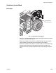
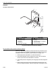
Oscillation Control Block
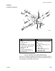
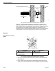
Fig. 7-21: Oscillation Control Block (Exploded View)
(Ref. Fig. 7-21) Follow the guidelines for cleanliness as stated in Section 5
of this manual. The following procedures are for the disassembly, cleaning,
and assembly of the oscillation control block.
MV0660
6
5
4
3
2
1
16
15
14
13
11
12
11
10
9
8
18
9
19
17
4
20
7
7
# Description
1Nut
2Coil
3 Solenoid Valve
4Seal Kit
5 Counter Balance Valve Cartridge
6 PO Check Valve (PC1 & PC2)
7 Orifice Plug, .040
8O-Ring
9 Hollow Hex O-Ring Plug, #4
10 Hollow Hex O-Ring Plug, #10
11 Backup Ring
# Description
12 O-Ring
13 Check Valve Cartridge, (CV3 &
CV4)
14 Piston Assy
15 Pressure Reducing Valve Car-
tridge, (PR)
16 Check Valve
17 Orifice Plug
18 Hollow Hex O-Ring Plug, #2
19 Orifice Plug, .080
20 Orifice Disc, .130