
Service Manual User guide


Frame Tilt and Oscillation
7-32
31200079
Removal
Oscillation Control Block
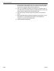
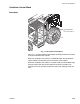
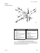
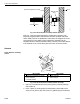
Fig. 7-20: Oscillation Control Block Installation
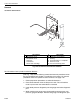
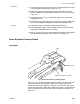
Rear Oscillation Lock Cylinder Installed on Machine
(Ref. Fig. 7-20) Use the following control block removal procedures when
the rear oscillation lock cylinder is installed on the machine. For removal
procedures when the cylinder has been removed, see page 7-33.
1. Follow preparation procedures as outlined in Section 3.
2. Place blocks between frame and top of rear axle. This will hold the
frame in place when the control block is removed.
3. Install brake pressure diagnostic port test gauge onto brake diagnostic
port.
4. While watching test gauge, press brake pedal numerous times until
pressure gauge reads 0 psi. Remove test gauge from diagnostic port.
MV0470
1
9
4
3
5
8
26
29
1
1
6
7
10
1
2
# Description
1 #6 Hydraulic Hose
2 #8 Hydraulic Hose
3Capscrew
4 Lockwasher
5 Check Valve Cartridge
# Description
6 Oscillation Control Block
7O-Ring
8 Rear Oscillation Lock Cylinder
9 Electrical Lead
10 Pressure Reducing Valve