
Service Manual User guide


Frame Tilt and Oscillation
7-4
31200079
Removal
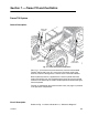
Frame Tilt Control Valve
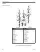
Fig. 7-3: Frame Tilt Control Valve Installation
(Ref. Fig. 7-3) The following procedure describes removal of the frame tilt
control valve.
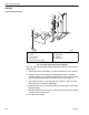
1. Follow preparation procedures as outlined in Section 3 of this manual.
2. Remove six (6) screws (Item 2) and flatwashers (Item 1) securing
control panel (Item 3) to operator’s compartment. Lift up rear of control
panel to expose lower portion of frame tilt control valve (Item 5).
3. Tag and disconnect six (12) hydraulic hoses (Items 4 and 9) at frame
tilt control valve. Cap hoses and fittings.
4. Note Position of two (2) tee fittings (Item 8) on back side of valve body.
Remove fittings.
5. Remove two (6) capscrews (Item 7) and starwashers (Item 6) retaining
control valve to control panel.
6. Lift valve up to remove.
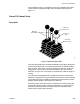
MV0650
7
6
5
4
3
1
2
8
9
p
1 Flatwasher
2Screw
3 Control Panel
41/4” Hoses
5 Frame Tilt Control Valve
p
6 Starwasher
7Capscrew
8 Fittings
93/8” Hoses