Operator & Safety Manual Keep this manual with machine at all times.
Revision Log Revision Log REVISION LOG March 9, 2005 - A - Original Issue of Manual July 12, 2005 - B - Revised pages 6, 23, 24, 27 & inside rear cover. February 23, 2009 - C - Revised covers and pages c, 30 & 31.
Read This First Read This First This manual is a very important tool! Keep it with the machine at all times. The purpose of this manual is to provide owners, users, operators, lessors, and lessees with the precautions and operating procedures essential for the safe and proper machine operation for its intended purpose. Due to continuous product improvements, JLG Industries, Inc. reserves the right to make specification changes without prior notification. Contact JLG Industries, Inc.
Read This First This product must comply with all safety related bulletins. Contact JLG Industries, Inc. or the local authorized JLG representative for information regarding safety-related bulletins which may have been issued for this product. JLG Industries, Inc. sends safety related bulletins to the owner of record of this machine. Contact JLG Industries, Inc. to ensure that the current owner records are updated and accurate. JLG Industries, Inc.
Read This First This Page Intentionally Left Blank d
TABLE OF CONTENTS Revision Log . . . . . . . . . . . . . . . . . . . . . . . . . . . . . . a Read This First. . . . . . . . . . . . . . . . . . . . . . . . . . . . . Operator Qualifications . . . . . . . . . . . . . . . . . . . . Modifications . . . . . . . . . . . . . . . . . . . . . . . . . . . . Other Publications Available . . . . . . . . . . . . . . . . b b b c Safety . . . . . . . . . . . . . . . . . . . . . . . . . . . . . . . . . . . . .1 Danger, Warning, & Caution: What They Mean . .
TABLE OF CONTENTS ii
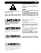
SAFETY SAFETY STANDARD W1038 W DANGER, WARNING, & CAUTION: WHAT THEY MEAN Hazards are identified by the “Safety Alert Symbol” and followed by a signal word: Danger, Warning, or Caution. The ASME/ANSI B56.6 safety standard for rough terrain forklift trucks defines safety requirements relating to the design, operation, and maintenance of these vehicles. DECALS The decals on the vehicle provide instructions for safe and correct operation.
SAFETY REFUELING SAFETY Never smoke near the vehicle during refueling. Do not permit anyone to be on the vehicle during refueling. Spilled fuel must be completely absorbed or evaporated before starting the engine. Make sure the fuel cap is in place before starting the engine. Never use an open flame when checking the fuel level in the tank. Never fill the fuel tank with the engine running. Make sure you have adequate ventilation during fueling.
SAFETY OPERATION SAFETY Before Leaving the Vehicle Unattended… Safe operation is the responsibility of the operator. Improper use of the vehicle can lead to dangerous situations for yourself, those around you, the vehicle and the work area. You must have safe working habits and be aware of hazardous working conditions. • • • Stop the engine. Block the wheels if parked on an incline. Lower the boom.
Always check clearances under power lines and overhead structures before driving under them. W1017 W1011 SAFETY Ensure that correct tire pressure and tire ballast levels are maintained. W1014 DO NOT operate the vehicle near energized power lines. Always contact the electrical power company when operating near power lines. The lines should be moved, insulated, disconnected, or de-energized and grounded before operating in the area. Keep all parts of the vehicle at least 10 feet away from power lines.
W1021 W1016 SAFETY W1020 Drive carefully and avoid sudden stops and changes of direction. W1015 Never place loads that exceed scaffold capacity or subject scaffold to unnecessary “shock” loads. W1022 Ensure that the load is stable and secure. Check to see that there are no loose articles that may fall off the fork. Don’t overload the vehicle. W1019 W1023 Never stack a load on uneven ground. Never add unauthorized counterweights. Always be aware of load width.
W1043 W1024 SAFETY Always pick up the load at its center of gravity. W1018 W1026 The vehicle can be levelled side to-side a total of 10° in each direction (18% grade). Any slope or grade that exceeds this is considered excessively steep. Avoid parking on slopes. If it is necessary to park on a slope, set the parking brake and block the wheels. When Traveling On Inclines… • Tilt the attachment back and raise only enough to clear the ground. • Avoid turning.
SAFETY Additional Safety Instructions: • Maneuver the vehicle carefully. Do not cause the load to shift or the vehicle to tip. • Slow down for wet and slippery surfaces and changes in terrain. • Turn the steering wheel smoothly and slow down when turning. • Do not make sharp turns at high speeds. • Take special care when traveling without a load. • Do not block access to fire lanes or fire equipment.
BEFORE OPERATING THE MACHINE CHECK THE EQUIPMENT Note: Before you begin your workday, take time to check (9) your vehicle and have all systems in good operational condition. Check the following: 9 Warning decals, special instructions, 9 9 9 9 9 9 9 9 9 service/lubrication schedule and operators manuals. Make sure they are legible and stored in the proper location. NEVER operate without a legible load chart. Engine oil level. Add oil as required. Radiator coolant level. Add coolant as required.
BEFORE OPERATING THE MACHINE DANGER KEEP ALL PARTS OF MACHINE AT LEAST 10 FEET FROM POWER LINES. CONTACTING ENERGIZED POWER LINES WILL CAUSE DEATH OR SERIOUS PERSONAL INJURY! PLAN YOUR WORK Before you operate, know how and where you will travel, turn and pickup, lift and place loads. Choose a smooth level route to prevent possible tipover or loss of load. If possible, avoid crossing… • Ruts. • Ditches. • Curbs. • Exposed railroad tracks.
BEFORE OPERATING THE MACHINE MOUNT AND DISMOUNT PROPERLY Always use “Three Point Contact” when mounting or dismounting the vehicle. “Three Point Contact” means that three out of four arms and legs are in contact with the vehicle at all times during mount and dismount. Clean your shoes and wipe your hands before mounting vehicle. Always use hand-hold and step when mounting. Never use control levers as a hand-hold when mounting or dismounting the vehicle.
BEFORE OPERATING THE MACHINE 11
INSTRUMENTS AND CONTROLS GAUGES AND LIGHTS 1 3 2 BOOM/ TRANSFER EXTEND LOCK CHECK ENGINE P 4 5 240 WATER 190 160 130 100 (7) Low Brake Pressure—Red lamp lights and buzzer sounds when service brake hydraulic system pressure drops below the safe operating level. Under normal conditions, the light and buzzer will go out quickly after engine start. If the light or buzzer does not go out or comes on during vehicle operation, shut off engine immediately, investigate, and repair before operating.
INSTRUMENTS AND CONTROLS 14 12 17 15 QUARTZ 00000 1 10 16 HOURS H1057 Hourmeter (12)Hourmeter—Located on the instrument panel to the left of the Gauge and Light Cluster. Registers total hours of vehicle operation. H1021 Ignition Switch Positions Note: The starter will not engage unless the park brake is applied and the shift selector is placed in the NEUTRAL position. IGNITION SWITCH The ignition switch has four positions: (14)OFF: The key may be removed or inserted only at this position.
INSTRUMENTS AND CONTROLS BRAKE PEDAL WARNING Read, understand, and follow the instructions starting on page 32 of this manual BEFORE using the Drive Lockout Override System. Failure to follow the instructions in this manual may result in death or serious personal injury! The drive lockout override switch (2) is located on the cab floor, to the left of the brake pedal. See “Stability Systems” on page 32 before using this switch.
INSTRUMENTS AND CONTROLS SHIFT SELECTOR Neutral Lock F 1 2 3 4 F N R 1 2 3 4 N R 4 H1022 Shift Selector The shift selector is located on the steering wheel column. It controls vehicle travel direction and transmission speed range. N D Direction Control Vehicle travel direction is controlled by moving the shift lever to one of three positions: H1023 FORWARD (F): Move the lever fully forward to select forward vehicle movement.
INSTRUMENTS AND CONTROLS STEER MODE SELECTOR 2 3 1 TRANSMISSION DECLUTCH OV0040 Transmission Declutch Switch The transmission declutch switch (1) is an internally lighted rocker switch located on the instrument panel, below the gauge cluster. Pressing the forward side of the switch activates the transmission declutch feature when the foot brake pedal is applied. This feature eliminates the need to shift to NEUTRAL before operating the hydraulic system at high engine speeds.
INSTRUMENTS AND CONTROLS Front Wheel Steer Mode Oblique Steer Mode V1002 V1003 Front Wheel Steer Mode Oblique Steer Mode Front Wheel Steer mode, also known as “2-Wheel Steer” mode, allows the operator to steer the vehicle in a conventional manner. The front wheels of the vehicle steer and the rear wheels remain in position. Oblique Steer mode, also known as “Crab Steer” mode, enables steering of the front and rear wheels in the same direction.
INSTRUMENTS AND CONTROLS V1010 V1013 Step 4 4. Turn the steering wheel to the left about one turn. Step 11 5. Select ROUND steer mode. 11. Drive the vehicle forward a short distance to check wheel tracking. 6. Turn the steering wheel to the right until it reaches the stop. This makes sure the rear wheels are fully against right stop. 12. Stop the vehicle and select the desired steer mode. Note: The above procedure can also be performed in the left direction. 7. Select FRONT WHEEL steer mode.
INSTRUMENTS AND CONTROLS JOYSTICK CONTROLS V1018 V1019 General Description Tilting Attachment Up Joystick The joysticks control hydraulic flow to the associated cylinders. Pulling back on the front joystick tilts the attachment upwards. Control is proportional: The more joystick movement, the greater the action. The speed of cylinder action is also affected by engine/hydraulic pump speed. Action is quicker at higher engine speeds.
INSTRUMENTS AND CONTROLS Rear Joystick The rear joystick controls boom elevation and extension. V1022 An auxiliary function is also available by pressing the button on top of the handle. See “Auxiliary Controls” on page 22 for further information. Extending the Transfer Carriage V1023 Moving the front joystick to the right extends the transfer carriage Lowering the Boom V1021 Moving the rear joystick forward lowers the boom.
V1025 INSTRUMENTS AND CONTROLS Extending the Boom V1026 Moving the rear joystick to the right extends the boom. Retracting the Boom Moving the rear joystick to the left retracts the boom.
INSTRUMENTS AND CONTROLS V1032 Auxiliary Controls Auxiliary Controls A switch is located on the top of the front & rear joysticks, under a protective rubber cap. Pressing this switch down with your thumb activates the auxiliary function. Hold the switch down while moving the joystick left and right. Functions for the tilting carriage using the front joystick are shown below as an example.
INSTRUMENTS AND CONTROLS TRANSFER CARRIAGE EXTENSION INDICATOR 60 80 80 BOOM ANGLE INDICATOR 60 0 -20 0 20 4 DEGREES -20 0 20 R1030 40 H1045 Boom Angle Indicator The boom angle indicator shows the angle of the boom relative to level ground. Use this indicator with the boom extension indicator, transfer carriage extension indicator, and vehicle load chart to determine correct boom lifting capacities. See “Sample Load Chart” on page 40.
INSTRUMENTS AND CONTROLS W1040 WARNING ALWAYS LEVEL MACHINE BEFORE RAISING BOOM. NEVER TILT FRAME WITH THE BOOM RAISED. MACHINE MAY TIP AND CAUSE DEATH OR SERIOUS PERSONAL INJURY! OUTRIGGER CONTROLS Right Outrigger Left Outrigger FRAME TILT CONTROL H1046 Outrigger Controls The outrigger control levers are located just in front of the frame tilt control lever. Moving an outrigger control lever to the right will lower the outrigger; moving it to the left will raise it.
INSTRUMENTS AND CONTROLS 25
GENERAL OPERATING PROCEDURES STARTING PROCEDURES SHUTDOWN PROCEDURES Before operating, walk completely around the vehicle. Make certain no one is under it, on it or close to it. Let all other workers and bystanders know you are preparing to start the vehicle. DO NOT start vehicle until everyone is clear. Correct shutdown is important to the safe operation of the vehicle. To start engine... 1. Start on level surface. 2. Be properly seated. 3. Set park brake. 4. Move shift selector to NEUTRAL position.
GENERAL OPERATING PROCEDURES FOLLOW SAFE OPERATING PROCEDURES WARNING ALWAYS LEVEL MACHINE BEFORE RAISING BOOM. NEVER TILT FRAME WITH THE BOOM RAISED. MACHINE MAY TIP AND CAUSE DEATH OR SERIOUS PERSONAL INJURY! ALWAYS check the load chart mounted in the vehicle before lifting a load. Lift only within the capacity of the vehicle as shown by the load chart. Never tilt the frame when the boom is raised. Operate the controls smoothly–don't jerk the hydraulic controls or steering wheel.
GENERAL OPERATING PROCEDURES If a slope is too steep to allow the frame to be leveled, do not raise the boom. The frame must always be level before raising the boom. WARNING When traveling over inclines, slopes or ramps… Tilt the attachment back and raised only enough to clear the ground. Avoid turning. If it cannot be avoided, turn slowly and with extreme caution. Travel straight up and down the grades. When loaded and traveling up or down grades, travel with the load uphill.
GENERAL OPERATING PROCEDURES 6. When the load is slightly higher than the landing point, SLOWLY stop the lift. . WARNING Do not ram the hydraulic lift cylinder to the end of its stroke. The jolt could spill the load resulting in death or serious personal injury. LIFTING PERSONNEL JLG strongly recommends that you DO NOT use the JLG vehicle as a personnel lift. It is designed for material handling ONLY. If personnel MUST be lifted, lift only in accordance with ASME/ANSI B56.6 1992 (or later), Para. 5.
GENERAL OPERATING PROCEDURES QUICK ATTACH Disconnecting an Attachment 1. Come to a complete stop on flat, level ground. 2. Set the park brake. 3. Raise the boom so attachment clears ground. 4. Extend the boom a short distance. 5. Lower the boom to rest the attachment on level ground. 6. Shut off engine. 10. Start the engine. Fully rotate quick attach (5) downwards by using the attachment tilt control. 7. Disconnect attachment hydraulic lines (if equipped). 11.
GENERAL OPERATING PROCEDURES Connecting an Attachment 1. With quick attach (5) rotated fully downwards, extend the boom until quick attach pivot pin (6) is properly aligned underneath the attachment (7). 5. Check to see that the lock plate (3) is engaged ahead of the attachment stop (4). WARNING MAKE SURE ATTACHMENT IS SECURELY CONNECTED TO QUICK ATTACH. ATTACHMENT MAY FALL AND CAUSE SERIOUS PERSONAL INJURY OR DEATH! 2. Raise the boom to engage the quick attach pivot pin (6) with the attachment (7). 6.
STABILITY SYSTEMS SYSTEM SAFETY DRIVE LOCKOUT OVERRIDE Never tamper with, modify, or bypass the stability systems installed on your JLG vehicle. Never disconnect or bypass pressure switches or proximity switches. Important: Read and understand the following instructions BEFORE using the Drive Lockout Override System! Theory of Normal Operation This vehicle is equipped with a stabilization system that does several things to increase lateral (side-to-side) stability.
STABILITY SYSTEMS When the boom angle is above 20° but below 40°, the rear axle cylinder is orificed, slowing movement of the frame on the rear axle. This increases the lateral (sideto-side) stability. When the boom angle is above 40°, the rear axle cylinder locks, preventing the frame rotating on the rear axle. This changes the stability diagram from a triangle to a rectangle (when viewed from above) and substantially increases the vehicle’s lateral stability.
STABILITY SYSTEMS BOOM/TRANSFER EXTEND LOCK SYSTEM The boom/transfer extend lock system is designed to increase stability of the vehicle by limiting how far the boom can be extended with the outriggers up. WARNING Do not disconnect or bypass the outrigger cylinder pressure switches. Do not restrict outrigger movement to simulate normal outrigger operation.
STABILITY SYSTEMS 35
FLUID & LUBRICANT SPECIFICATIONS GENERAL FLUID AND LUBRICANT SPECIFICATIONS General Fluid & Lubricant Specifications System or Component Fuel System1 Fluid or Lubricant Specification See “Fuel Requirements” Hydraulic System Tractor Hydraulic Mobilfluid® 424 Fluid Engine Cooling System See engine manufacturer’s operating manual.
FLUID & LUBRICANT SPECIFICATIONS TRANSMISSION OIL SPECIFICATIONS FUEL REQUIREMENTS The following table shows approved lubricants and associated temperature ranges for use with ZF 4WG series transmission. Transmission Oil Selection Chart ZF 4WG-98TC Transmissions General Diesel fuels are blended to meet the local temperature requirements. The standard grades are: 1. 1D for temperatures -22 to +86 °F (-30 to +30 °C). 2. 2D for temperatures +14 to +122 °F (-10 to +50 °C) Min. Oil Min.
SERVICE/LUBRICATION SCHEDULE 9 7 20 6 20 20 12 12 8 24 21 16 24 22 14 10 16 11 17 24 17 15 18 17 25 21 13 8 19 23 4 5 23 3 13 22 1 2 19 OV0050 38
SERVICE/LUBRICATION SCHEDULE SYSTEM CAPACITIES AND PRESSURES HYDRAULIC RESERVOIR 47 GALS TIRES 14.00 × 24 HYDRAULIC SYSTEM & RESERVOIR 65 GALS FUEL TANK 36 GALS PRESSURE HYDRO-FILL TIRES SHOULD BE FILLED TO APPROXIMATELY 75% FULL (55 GALLONS/596LB) OF CALCIUM CHLORIDE TIRE FILL. COOLING SYSTEM 18 QTS ENGINE CRANKCASE DEERE 4 CYL. 14 QTS TRANSMISSION DRAIN/REFILL (APPROX.) 19 QTS FRONT AXLE DIFFERENTIAL 9.5 QTS PLANETARY HUB (EACH) 54 OZ REAR AXLE DIFFERENTIAL 10.
SAMPLE LOAD CHART MAXIMUM BOOM LOAD CAPACITIES AT 24" LOAD CENTER, FOR LIFT AND REACH POSITIONS IN POUNDS AND FEET WITH METRIC CONVERSIONS. TRANSACTION 80" (203 CM) 12 40 MANUFACTURER'S RECOMMENDED CAPACITIES ARE IN CONFORMANCE WITH ANSI/ASME B56.6 STABILITY TESTS USING STANDARD HOMOGENEOUS CUBES 4' × 4' × 4'. INDICATES REAR 11 OSCILLATION LOCK 35 MANUFACTURER'S RECOMMENDED LOADS AND ANGLES SHOWN ARE AT THE HORIZONTAL CENTER OF GRAVITY OF THE ABOVE CUBE.
CALIFORNIA PROPOSITION 65 BATTERY WARNING Battery posts, terminals and related accessories contain lead and lead compounds, chemical known to the State of California to cause cancer and reproductive harm. WASH HANDS AFTER HANDLING! CALIFORNIA PROPOSITION 65 EXHAUST WARNING Diesel Engine exhaust and some of its constituents are known to the State of California to cause cancer, birth defects and other reproductive harm.
An Oshkosh Corporation Company JLG Industries, Inc. 1 JLG Drive McConnellsburg PA. 17233-9533 USA Phone: +1-717-485-5161 Customer Support Toll Free: 1-877-554-5438 Fax: +1-717-485-6417 JLG Worldwide Locations JLG Industries (Australia) P.O. Box 5119 11 Bolwarra Road Port Macquarie N.S.W. 2444 Australia Phone: +61 265 811 111 Fax: +61 265 810 122 JLG Latino Americana Ltda. Rua Eng.