Instruction Manual Rerailing Equipment LUKAS traversing system 1430000085 EN E Edition 09.2014 09.
Content Page 1. Danger classifications 4 2. Product safety 5 3. Proper use 8 4. Components and functions 9 4.1 Description 9 4.2 Hydraulic supply to the cylinders 10 5. Connecting the hydraulic equipment 10 5.1 Basic aspects 10 5.2 Coupling the quick-disconnect couplings 11 6. Operation 12 6.1 Setting up the LUKAS traversing system 12 6.2 Start-up 25 6.3 Controlling the LUKAS traversing system with anchor pin 26 6.4 Controlling the DUO traversing cylinder with anchor cylinder 7.
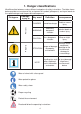
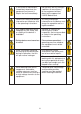
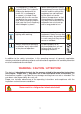
1. Danger classifications We differentiate between various different categories of safety instructions. The table shown below provides an overview of the assignment of symbols (pictograms) and signal words to the specific danger and the possible consequences.
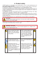
2. Product safety LUKAS products are developed and manufactured to ensure the best performance and quality when used as intended. The safety of the operator is the most important consideration in product design. Furthermore, the operating instructions are intended to help in using LUKAS products safely.
In the event of malfunctions, immediately deactivate the equipment and secure it. Repair the fault immediately. Do not carry out any changes (additions or conversions) to the equipment without obtaining the approval of LUKAS beforehand. Observe all safety and danger information on the device and in the operating instructions. All safety and danger information on the device must always be complete and in a legible condition.
The equipment is filled with hydraulic fluid. This hydraulic fluid can be detrimental to health if it is swallowed or its vapour is inhaled. Direct contact with the skin must be avoided for the same reason. Also, when handling hydraulic fluid, note that it can negatively affect biological systems. When working with or storing the equipment, ensure that the function and the safety of the equipment are not impaired by the effects of severe external temperatures or that the equipment is damaged in any way.
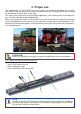
3. Proper use The components of the LUKAS traversing system are especially designed for re-railing technology. They are used for rerailing of rail-bound vehicles. Derailed vehicles can be lifted up and moved at right angles to the track. The accessories necessary for the particular application, such as base plate, multistage sets etc., must be used during each deployment.
4. Components and functions 4.1 Description 4.1.1 Rerailing bridge The rerailing bridge is placed at right angles over the tracks and provides the support and moving surface for the LUKAS rolling carriages and the DUO traversing unit. If one bridge is not long enough, a second bridge can be screwed on by means of joining elements. The integrated anchor cylinder locates as a locking pin in the arresting openings in the top of the rerailing bridge.
4.2 Hydraulic supply to the cylinders Only the specified LUKAS hydraulic power packs (motor pumps) or suitable LUKAS hand pumps can be used to drive the equipment. If the pump unit is a different make, you must make sure that it complies with LUKAS specifications, otherwise potential dangers may occur which are not the responsibility of LUKAS. Ensure in particular that the maximum permissible operating pressure for the connected LUKAS equipment is not exceeded.
5.2 Coupling the quick-disconnect couplings The device is connected to the hydraulic pump without risk of misconnection using monocoupling halves (female and male coupling). X Y Before coupling, remove dust caps and then pull back and hold the locking sleeve of the female coupling half (position X). Connect the male and female couplings and release the locking sleeve. Then turn the locking sleeve to position Y. The connection has been made and locked. Uncoupling is done in the reverse order.
6. Operation 6.1 Setting up the LUKAS traversing system 6.1.1 General The LUKAS traversing system consists of several individual components. Appropriate combination of the individual components can be used to set up various different total systems. With some of these overall systems, not all the individual components are required, and on others you will need several of the individual components.
recommends the use of suitable piston guard plates for this reason, as otherwise there is a risk of damage to the piston rod or the cylinder. A convex piston guard plate distributes the load evenly over the piston area again. If several cylinders/rolling carriages are used simultaneously, the load should be distributed as evenly as possible over all cylinders/rolling carriages.
and achieve safe power introduction - Please ensure that the load is applied centrally to the piston rod. - Stability and load application is improved if you use load distribution plates. Distribution plates permit an angle of inclination of 5 °. ATTENTION! Observe the permissible angle of inclination when lifting the vehicle! 6.1.3 Setting up the rerailing bridges The bridge is placed across the tracks and carefully supported by wooden planks.
- The maximum load of the bridge connecting elements (optional) is not exceeded: Bridge height Support width Max. load [mm] [m] [kN] [in.] [ft.] [lbs.] 85 1 20 3.35 3.28 4500 140 1 200 5.51 3.28 45000 184 1 300 7.24 3.28 68000 - the bridge is horizontally aligned: The angle of the bridge may not exceed 3°. If one bridge is not long enough, a second bridge can be screwed on by means of joining elements.
6.1.5 Setting up hydraulic cylinders on the rolling carriages The hydraulic cylinders are placed centrally on the top carrier plate of the rolling carriage if they are to be moved along with the lifted load (see illustration below). CAUTION / ATTENTION! When traversing a load lifted by a hydraulic cylinder (upright on the rolling carriage), you need to ensure that the load cannot tip over during traversing.
6.1.6 Setting up the traversing cylinder with fixed anchor pin Insert the traversing cylinder with the fixed anchor pin in one of the suitable mounts (slotted holes) in the rerailing bridge, and hook it into the middle mount for the rolling carriage with the piston rod head (see illustration below). It may be necessary to move the rolling carriage slightly to allow the cylinder head to be hooked in.
6.1.7 Setting up the traversing cylinder with anchor cylinder (double-acting) Insert the traversing cylinder with the head of the anchor cylinder in one of the matching mounts in the rerailing bridge. To do this you must slide the slide plate at the back end of the traversing cylinder upwards slightly. Then suspend the traversing cylinder with the piston rod head in the middle mount in the rolling carriage (see illustration below).
Now pull the slide plate upwards to the stop and apply the guide plates on the right and left on the traversing cylinder. Move the applied guide plates towards the cylinder head and slide the slide plate back down. The traversing cylinder is now secured against lateral traversing and against lifting.
6.1.8 Setting up and adjusting the connecting rods The distance between the load lift points must be set precisely using the connecting rods. For this reason you have a coarse and fine adjustment facility. Coarse setting of the connecting rods: 1. Remove the locking pin. 2. The coupling rod can now be pulled out and this allows coarse setting of the distance of the rolling carriages. The hole in the coupling rod must line up with a hole in the pipe in order to be able to insert the locking pin. 3.
Fine setting of the connecting rods: The fine setting is carried out at the other end of the pipe. Insert a metal rod (ø8 mm) or a similar tool into the cross-hole of the adjusting bolt and unscrew it (anticlockwise), until the desired distance is reached. The adjusting bolt can be unscrewed maximum 80 mm in order to carry out the fine adjustment. Connecting two rolling carriages: Two connecting rods are always required for connecting two rolling carriages.
NOTE: If the traversing cylinder is to operate between the two rolling carriages, then the connecting rods must be mounted only after setting up the traversing cylinder. 6.1.9 Examples of traversing systems CAUTION / ATTENTION! If there is any doubt about the set-up of your traversing system you must contact a relevantly trained safety expert or LUKAS direct. NOTE: When setting up the traversing cylinder in combination with two rolling carriages there are two set-up possibilities: 1.
The following gives a few examples of setting up of the traversing system: 1. Traversing system with a rolling carriage and separate load lifting (recommended variant) Components required: - 1 Hydraulic power pack - 1 Control table - Separate load lifting system (e.g. Hydraulic cylinder with required accessories) - Rerailing bridge - 1 Rolling carriage - 1 Traversing cylinder - Packing material (e.g. hardwood beams) - Hose lines 2.
Example illustration two point lifting 3. Traversing system with a rolling carriage and hydraulic cylinder standing on it Components required: - 1 Hydraulic power pack 1 Control table 1 Rolling carriage 1 Traversing cylinder 1 Hydraulic cylinder Packing material (e.g. hardwood beams) Hose lines 4.
6.2 Start-up ATTENTION! During commissioning you must observe all the instructions and regulations from the separate operating instructions for all the components that you use in the rerailing system that is to be commissioned! Work required before commissioning: Before commissioning you must carry out a visual check for damage and leaks on all components being used.
CAUTION / ATTENTION! Make sure that there are no persons remaining in the danger area! Observe the individual rerailing concepts of the vehicle manufacturer. Only then should you commission the rerailing system! 6.
9. Put the vehicle down with the separate LUKAS load lifting system. NOTE: If the traversing movement of the rerailing bridge is not adequate, the entire traversing system is relocated. When assembling the traversing system for the first time, make sure that allthe required preconditions in the Chapter "Setting up the LUKAS traversing system" are fulfilled! You can then repeat the procedures 1 to 9. 10. Then remove the components of the traversing system being used again. 6.3.
7. Then remove the components of the traversing system being used again. 6.4 Controlling the DUO traversing cylinder with anchor cylinder CAUTION / ATTENTION! The vehicle ton be rerailed must be secured against rolling away, slipping and tipping over in accordance with the regulations! Observe the individual rerailing concepts of the vehicle manufacturer. 6.4.1 Traversing with external load lifting: Procedure: 1.
CAUTION / ATTENTION! When traversing several times make sure that the rolling carriages are not pushed by the rerailing bridge! 11. Move your separate load lifting system for putting down so that the vehicle to be rerailed can be lifted safely again. If it is not aligned horizontally, you must secure the rerailing bridge against rolling away, slipping and tipping over, in order to prevent inadvertent movement of the vehicle to be rerailed! 12.
CAUTION / ATTENTION! When traversing several times make sure that the rolling carriages are not pushed by the rerailing bridge! 8. Items 6 and 7 can be repeated "as often as you need". 9. Put the vehicle down on the track by retracting the hydraulic cylinder standing on the rolling carriage. The vehicle must remain secured against rolling away, slipping and tipping over! 10. Remove the hydraulic cylinder(s) from the rolling carriage(s). 11. Retract the traversing cylinder again. 12.
8. Maintenance and service A visual inspection must be carried out after every use, but at least once a year. Every 3 years, or if there is any doubt regarding the safety or reliability of the equipment, a functional test must also be performed. (Please also observe the relevant valid national and international regulations pertaining to service intervals of hydraulic equipment).
NOTE: You should always contact LUKAS or an authorised dealer before using couplings from another manufacturer. ATTENTION! Because LUKAS devices are designed for the highest performance, only components may be replaced that are listed in the spare parts lists of the corresponding device. Other components in the device may only be replaced if: - You have participated in an appropriate LUKAS service training course.
9.3 Repairs 9.3.1 Coupling replacement The couplings must be replaced if: - there is external damage, - the locking does not function, - hydraulic fluid continues to leak in the coupled/uncoupled state. WARNING / CAUTION / ATTENTION! Never repair couplings: they must be replaced by genuine LUKAS parts! During assembly tighten the coupling to a torque of MA = 40 Nm. Procedure: 1. Remove the coupling. 2. Place a new coupling in position and tighten to a torque of MA = 40 Nm. 9.3.
9.3.4 Replacing the handles on traversing cylinder Any damaged or broken handles must be replaced. Procedure for fixing directly on the traversing cylinder: 1. Release the screws on the handle and remove them, together with the washers underneath. 2. You can now remove the handle and replace it. 3. Assembly is in the reverse order. Bolt Bolt Washer Washer Handle Procedure for fixing with clamps: 1. Release the screws and nuts and remove them. 2.
9.3.5 Slider plate replacement on the traversing cylinder with anchor cylinder A damaged, bent or broken slider plate must be replaced. Procedure: 1. Release the screws on the anchor cylinder and remove them. 2. You can now remove the slider plate and replace it. 3. Assembly is in the reverse order. Make sure that the pin mounted in the anchor cylinder can move in the narrow slotted hole of the slider plate. Pin Narrow slotted hole Bolts 9.3.
10. Troubleshooting Fault Check Cylinder piston moves Are the hoses slowly or jerkily when connected activated properly? Cause Solution Air in the Bleed the pump system hydraulic system (see operating instructions for hydraulic power packs) Does the pump unit work? Pressure in control table OK? Read the pressure gauge Visual check of hydraulic oil Device doesn’t perform at its given power Hydraulic oil too viscous because of ambient temperature.
Fault Check Cause Solution Damage on the surface of the hydraulic hose lines Mechanical damage or contact with aggressive agents Replace hoses Hydraulic fluid leaks on the piston rod Defective rod seal Repair by an authorised dealer, by personnel specially trained by LUKAS, or by LUKAS itself Damage to the piston Leak from the couplings Is the coupling damaged? Coupling defective Coupling must be replaced immediately Contact an authorised LUKAS dealer or the LUKAS Customer Service Department di
11. Technical data Because all values are subject to tolerances, there may be small differences between the data for your device and the data in the following tables! 11.1 Traversing cylinder Device type TC170 90-350F Item number 70-30-20 Dimensions lxwxh Value 653 x 156 x 177 mm 25.7 x 6.2 x 6.9 in. Length, extended Force / Pushing Force / Pulling Stroke Operating pressure Total in. 176 kN 39600 lbf. 92 kN 20700 lbf. mm in. 53 MPa 7700 psi 509 cm³ 31.1 cu.in.
Device type TC170 90-350 Item number 70-30-10 Dimensions lxwxh Value Units Remarks 668 x 363 x 197 mm retracted 26.3 x 14.3 x 7.7 in. 988 mm 38.9 in. Length, extended Force / Pushing 176 kN 39600 lbf. 92 kN 20700 lbf. 320 mm 12.6 in. 53 MPa 7700 psi 509 cm³ 31.1 cu.in. -20 … +55 °C -4 … +131 °F 25 kg 55.1 lbs. Force / Pulling Stroke Operating pressure Total max.
Device type TC170 200-350 Item number 70-30-30 Dimensions lxwxh Value Units Remarks 685 x 370 x 214 mm retracted 27.0 x 14.6 x 8.4 in. 1007 mm 39.7 in. 337 kN 75800 lbf. 207 kN 46500 lbf. 322 mm 12.7 in. Length, extended Force / Pushing Force / Pulling Stroke Operating pressure Total max. 53 MPa 7700 psi 793 cm³ 48.4 cu.in. -20 … +55 °C -4 … +131 °F 44 kg 97 lbs.
11.2 Rolling carriage Device type RC-700/350 Item number RC-1000/350 840720640 840721631 Dimensions (L x B x H) [mm] 390 x 380 x 130 360 x 380 x 154 [in.] 15.4 x 15 x 5.12 14.2 x 15 x 5.5 max. width of rerailing bridge [mm] 350 350 [in.] 13.8 13.8 max. permitted load [kN] 750 1000 Weight [lbf.] 168600 224800 [kg] 41.5 62 [lbs.] 91.7 139 11.3 Rerailing bridges Device type 1.1 m / 85 mm Item number Dimensions (L x B x H) [mm] [in.] 2.2 m / 85 mm 3.
Device type 1.1 m / 184 mm 2.2 m / 184 mm Item number 840726381 840726382 Dimensions (L x B x H) Weight [mm] 1100 x 350 x 184 2200 x 350 x 184 [in.] 43.3 x 13.8 x 7.24 86.6 x 13.8 x 7.2 [kg] 70 140.5 [lbs.] 154 310 3.3 m / 184 mm 4.4 m / 184 mm Device type Item number Dimensions (L x B x H) Weight 840726383 840726384 [mm] 3300 x 350 x 184 4400 x 350 x 184 [in.] 130 x 13.8 x 7.24 17.3 x 13.8 x 7.24 [kg] 211 281 [lbs.] 465 620 11.
11.5 Recommended hydraulic fluids Mineral oil DIN ISO 6743-4 for LUKAS hydraulic equipment Oil temperature range Oil designation Viscosity rating Remarks A -24 .... +30°C HL 5 VG 5 B -18 .... +50°C HM 10 VG 10 C -8 .... +75°C HM 22 VG 22 D +5 .... +80°C HM 32 VG 32 E -8 .... +70°C HF-E15 VG 15 Bio-oil Oil temperature range Oil designation Viscosity rating Remarks A -11.2 .... +86°F HL 5 VG 5 B -0.4 .... +122°F HM 10 VG 10 C +17.6 .... +167°F HM 22 VG 22 D +41.0 ....
12.
13.
Please dispose of all packaging materials and removed items properly. LUKAS Hydraulik GmbH A unit of the IDEX Corporation Tel.: (+49) 0 91 31 / 698 - 0 Fax.: (+49) 0 91 31 / 698 - 394 e-mail: lukas.info@idexcorp.com www.lukas.com Made in GERMANY LUKAS_traversing_system_manual_143000085_en.