Instruction manual for rescue equipment Hose reels 176250085 EN Edition 10.
Content Page 1. Hazard classes 4 2. Product safety 5 3. Proper use 8 4. Description 9 4.1 General information 9 4.2 Single hose reel 9 4.3 Double hose reel 10 5. Connecting the equipment 11 5.1 On the side of the hydraulic unit 11 5.2 On the side of the equipment 11 5.3 Coupling the mono-couplings 12 6. Operation 13 6.1 Safety notes 13 6.2 Start-up 14 6.3 Parking brake 14 6.4 Unrolling 16 6.5 Coiling 16 7.
11. Technical Data 28 11.1 General reel identification 28 11.2 Maximum operating pressure 28 11.3 Technical data for the hose reels 29 11.4 Hydraulic fluid recommendation 33 11.5 Operating and storage temperature range 33 12. EC Declarations of conformity 34 13.
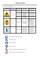
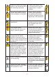
1. Hazard classes We distinguish between various categories of safety notes. The table below gives you an overview of the assignment of symbols (pictograms) and key words to the specific hazard and possible consequences.
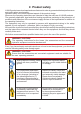
2. Product safety LUKAS products are developed and manufactured in order to guarantee the best performance and quality when used properly. Operator safety is the most important aspect of the product design. Moreover, the operating instructions are intended to help the safe use of LUKAS products. The generally applicable, legal and other binding regulations pertaining to the prevention of accidents and protection of the environment apply and are to be implemented in addition to the operating instructions.
Observe all safety and danger notes on the equipment and in the operating instructions. All safety and danger notes on the device are to be kept complete and in a legible condition. Any mode of operation which impairs safety and/or stability of the equipment is forbidden! Comply with all specified dates or dates specified in the operating instructions pertaining to regular controls / inspections on the equipment.
The generally applicable, legal and other binding national and international regulations pertaining to the prevention of accidents and protection of the environment apply and are to be implemented in addition to the operating instructions. W A R N I N G / C A U T I O N ! The equipment is to be used exclusively for the purpose stated in the operating instructions (see chapter “Proper Use”). Any other or further use is not considered proper use.
3. Proper use The LUKAS hose reels are used for mounting extension hose pairs between the hydraulic supply and the working equipment. The extension hose pairs are connected to the hose reel and coiled onto the drum. The use of a LUKAS hose reel with extension hose pairs enables a greater distance between the hydraulic supply and the equipment. This allows the hydraulic unit to stay on the emergency vehicle, for example.
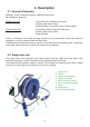
4. Description 4.1 General information Basically, a reel comprises a carrier, shaft and hose drum. We distinguish between: Single hose reel: - Connection of a extension hose pair - Delivery with carrier frame - Parking brake, fix mounted, flap-in crank handle Double hose reel: - Connection of two extension hose pairs - Delivery with carrier frame - Parking brake Coiling / unrolling of all models is being carried out by a hand crank, which can either be plugged in or is fix connected with the hose drum.
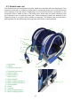
4.3 Double hose reel The double hose reel comprises one carrier frame and one shaft with two hose drums. Two extension hose pairs or extension hoses can be connected to the reel on the device side (one extension hose per drum). Depending on the connector version, connection on the equipment side is made by one or two short return hoses and one short extension hose per extension hose or extension hose pair. These connecting hoses are attached to the hydraulic pump or a control unit by means of couplings.
5. Connecting the equipment REMARK: Different couplings than mono-couplings, like quick-disconnect-couplings, are possible when using available adapter kits. Also the direct screw connection into the pump connection block of the power unit is possible. The adapter kits can be ordered via the LUKAS optional equipment.
5.3 Coupling the mono-couplings The equipment is connected to the hydraulic pump via mono-coupling halves (male and female). dust protection caps mono-coupling halve (male) mono-coupling halve (female) Before coupling, remove dust protection caps, then connect male and female, and turn the locking sleeve of the female to direction „1“ until the locking sleeve locks into place. The connection is now in place and secure. Decoupling is by turning the locking sleeve to direction „0“.
6. Operation 6.1 Safety notes World-wide, safety guidelines pertaining to the specific country are to be observed and complied with. In the Federal Republic of Germany, regular safety inspections according to the regulations of the Gesetzlichen Unfallversicherung (GUV; connoted ‘Legal accident insurance’) are mandatory.
6.2 Start-up Before start-up and following repairs, the hose assemblies of the hose reel must be deaerated: - Connect the hose reel to the hydraulic pump (see chapter “Connecting the equipment”). CAUTION! The working equipment has to be disconnected! - Switch on the hydraulic unit and pressurize the supply hoses for some time. - Switch the hydraulic unit to depressurized circulation or switch it. If necessary, you have to top-up hydraulic fluid.
6.3.2 Parking break SHR The parking break shall prevent that the extension hose pairs unroll during transport! To unlock or release the break pull at the knob and turn it about 90°. To activate the break turn the knob again about approx. 90° until it engages automatically. 90° 90° 6.3.3 Parking break SHR The crank is supposed to make coiling easier! To make the curl ready for use, pull at the crank handle, turn it about 90° outwards until it engages.
6.4 Unrolling To unroll, pull at the extension hoses until the required length has been unrolled from the hose reel. CAUTION! For unrolling the hose from the hose reels, the parking brake must first of all be released. This prevents damage to the reel and the hoses. 6.5 Coiling REMARK: We recommend the use of the hand crank for coiling the hose! - First of all, put the hand crank onto the shaft of the hose reel. Release the parking break. Aligning the hose simplifies the coiling of the hose.
7.4 Hose reel Coil the extension hose pairs onto the hose reel. Apply the parking brake on double hose reels. Apply the parking brake and flap in the crank handle on single hose reels. 8. Maintenance and service A visual inspection is to be carried out after every use: however, at least one visual inspection is to be carried out annually. A function test is also to be carried out every three years or should there be any doubt regarding the safety or reliability of the equipment.
9. Repairs 9.1 General information Servicing may only be carried out by the manufacturer or personnel trained by the manufacturer and by authorised LUKAS dealers. Only LUKAS spare parts may be used to replace all components (see spare parts list) since special tools, assembly advice, safety aspects, inspections might have to complied with (see also chapter “Maintenance and Service”).
9.2 Preventative service 9.2.1 Care regulations The exterior of the equipment is to be cleaned from time to time in order to protect it from external corrosion. Oil is to be applied to the metallic surfaces. 9.2.2 Function and load test If there is any doubt regarding the safety or reliability of the equipment, a function and load test must also be performed. 9.2.3 Changing the hydraulic fluid - The hydraulic fluid must be changed after after three years at the latest.
9.3 Repairs 9.3.1 Changing or tightening connection hoses Hose assembly of the supply and/or return hose leaks or hoses are defective. Tighten the hose connections on the shaft. (CAUTION! Observe torque of MA = 40 Nm/29.5 lbf∙ft!) 9.3.2 Changing or tightening extension hose pairs Hose assembly of the supply and/or return hose leaks or hose pairs are defective. Pull back the protective cover and tighten the hose connections on the elbows. (CAUTION! Observe torque of MA = 40 Nm/29.
9.3.3 Mono-couplings The mono-couplings must be replaced in the event of: - external visible damage, - the locking device not working, - hydraulic fluid continually leaking in a coupled/uncoupled state. WARNING / CAUTION! Never repair couplings: they are to be replaced by original LUKAS parts! Procedure: 1. Remove the cover from the couplings. 2. Loosen the connection nuts of the hose assembly and remove the coupling. 3.
11.3.5 Elbows on the single and double hose reels The elbows must be replaced in the event of: - external visible damage, - hydraulic fluid continually leaking on the elbow pipes. Procedure: 1. Remove the extension hose pairs. 2. Loosen the elbow and remove it. 3. Position the new ellbow and tighten it with a torqu of MA = 40 Nm/29.5 lbf∙ft. CAUTION! Take care that the elbows are always mounted in the correct oriented manner (see illustration on the right).
9.3.6 Changing the hose drum on the single hose reel Damaged hose drums must be immediately replaced. Before you can change the hose drums, however, you must dismantle the extension hose pairs! Procedure: 1. Remove the two fixing bolts and lock washers of the parking break. 2. Remove the three fixing bolts and lock washers of the crank. 3. Remove the hose drum and replace it with a new one. 4. Assembly is now carried out in reverse order.
9.3.8 Parking brake on the double hose reel If the parking brake on the double hose reel is damaged / non-functional, it must be replaced Procedure: 1. Remove bolts, washers, lock washers and nuts. 2. Remove the damaged parking brake D and replace it with a new one. 3. Assemble screws, washers and nuts, and tighten. Find further details on disassembling and assembling in the spare parts list. 9.3.9 Labels All damaged and/or illegible labels (safety notices, type plate, etc.) must be renewed.
10. Troubleshooting Trouble Control Equipment doesn’t Hose assemblies move when activated connected properly? Does the pump unit work? Cause Hose assemblies not connected Solution Reaffix hose assemblies or recouple them Equipment or See separate hydraulic unit operating instructions defective for hydraulic unit or equipment.
Trouble Control Leakage of hydraulic Hose extension fluid in the inner area pairs defective? of the hose reel. Connection of the hoses tighten? Leakage on the connection between elbow and shaft? Leakage of hydraulic fluid on the connections between connection hoses and reel shaft. Connection hoses defective? Solution Replace hoses Hoses not tightened properly onto the elbows. Defective elbow / defective sealing below the elbow Tighten the screwed connection between hoses and elbow.
If it isn’t possible to rectify the malfunctions, inform an authorised LUKAS dealer or the LUKAS customer service department immediately! The address for the LUKAS customer service department is: LUKAS Hydraulik GmbH Weinstraße 39, Postfach 2560, D-91058 Erlangen D-91013 Erlangen Tel.: (+49) 09131 / 698 - 348 Fax.
11. Technical Data Since all values are subject to tolerances, minor differences may occur between the data on your equipment and the data listed here! 11.1 General reel identification DHR 20 - 66 - 1,5 Type of hose reel SHR = single hose reel DHR = double hose reel Length of the short supply hose pairs Length of the extension hose pairs in [m] Length of the extension hose pairs in [ft.] 11.2 Maximum operating pressure The max.
11.3 Technical data for the hose reels Device type SHR xx-xx-1,5 Reference no. 81-60-10 Dimensions Operating pressure L x W x H 434 x 327 x 490 max. mm 17.1 x 12.9 x 19.3 in. 70 MPa 10000 psi m Hose length ft Number of connectable devices max. Number of hoses, pump side Number of connections, pump side Weight max. 1 Reel without hose Streamline® quickdisconnect 1x2 Connection hoses, 1.5 m / 4.9 ft long 1 Streamline® quickdisconnect 7.5 kg 16.5 lbs. 29 incl.
Device type SHR 15-50-1,5 Reference no. 81-60-15 Dimensions Operating pressure L x W x H 434 x 327 x 490 max. Hose length Number of connectable devices max. Number of hoses, pump side Number of connections, pump side Weight max. mm 17.1 x 12.9 x 19.3 in. 70 MPa 10000 psi 15 m 50 ft 1 Streamline® quickdisconnect 1x2 Connection hoses, 1.5 m / 4.9 ft long 1 Streamline® quickdisconnect 15 kg 33.1 lbs. 30 incl.
Device type SHR 20-66-1,5 Reference no. 81-60-20 Dimensions Operating pressure L x W x H 434 x 327 x 490 max. Hose length Number of connectable devices max. Number of hoses, pump side Number of connections, pump side Weight max. mm 17.1 x 12.9 x 19.3 in. 70 MPa 10000 psi 20 m 66 ft 1 Streamline® quickdisconnect 1x2 Connection hoses, 1.5 m / 4.9 ft long 1 Streamline® quickdisconnect 18 kg 38.6 lbs. 31 incl.
Device type DHR 20-66-1,5 Reference no. 81-61-20 Dimensions Operating pressure L x W x H 445 x 385 x 400 max. Hose length Number of connectable devices max. Number of hoses, pump side Number of connections, pump side Weight max. mm 17.5 x 15.2 x 15.8 in. 70 MPa 10000 psi 20 m 66 ft 2x1 Streamline® quickdisconnect 2x2 Connection hoses, 1.5 m / 4.9 ft long 2x1 Streamline® quickdisconnect 35,8 kg 78.9 lbs. 32 incl.
11.4 Hydraulic fluid recommendation Mineral oil DIN ISO 6743-4 for LUKAS hydraulic equipment and others Oil temperature range -24 .... +30°C -18 .... +50°C -8 .... +75°C +5 .... +80°C -8 .... +70°C Oil code HL 5 HM 10 HM 22 HM 32 HF-E15 Viscosity rating VG 5 VG 10 VG 22 VG 32 VG 15 Remarks A B C D E Oil code HL 5 HM 10 HM 22 HM 32 HF-E15 Viscosity rating VG 5 VG 10 VG 22 VG 32 VG 15 Remarks A B C D E Oil temperature range -11.2 .... +86°F -0.4 .... +122°F +17.6 .... +167°F +41.0 .... +176°F +17.6 .
12.
13. Notes Please dispose all packaging materials and dismantled parts properly LUKAS Hydraulik GmbH A Unit of IDEX Corporation Tel.: (+49) 0 91 31 / 698 - 0 Fax.: (+49) 0 91 31 / 698 - 394 e-mail: lukas.info@idexcorp.com www.lukas.com Made in GERMANY hose_reels_manual_176250085_en.