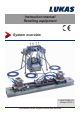
Instruction manual Rerailing equipment System overview 1490000085 EN Edition 09.
Content Page 1. Danger classifications 4 2. Product safety 5 3. Proper use 8 4. System description 9 4.1 System and components 9 4.2 Example scenario 1 - Single point lifting 10 4.3 Structure and process - Single point lifting 11 4.4 Example scenario 2 - Two point lifting 16 4.5 Structure and process - Two point lifting 17 5.
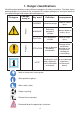
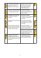
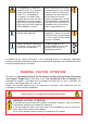
1. Danger classifications We differentiate between various different categories of safety instructions. The table shown below provides an overview of the assignment of symbols (pictograms) and signal words to the specific danger and the possible consequences.
2. Product safety LUKAS products are developed and manufactured to ensure the best performance and quality when used as intended. The safety of the operator is the most important consideration in product design. Furthermore, the operating instructions are intended to help in using LUKAS products safely.
In the event of malfunctions, immediately deactivate the equipment and secure it. Repair the fault immediately. Do not carry out any changes (additions or conversions) to the equipment without obtaining the approval of LUKAS beforehand. Observe all safety and danger information on the device and in the operating instructions. All safety and danger information on the device must always be complete and in a legible condition.
The equipment is filled with hydraulic fluid. This hydraulic fluid can be detrimental to health if it is swallowed or its vapour is inhaled. Direct contact with the skin must be avoided for the same reason. Also, when handling hydraulic fluid, note that it can negatively affect biological systems. When working with or storing the equipment, ensure that the function and the safety of the equipment are not impaired by the effects of severe external temperatures or that the equipment is damaged in any way.
3. Proper use The LUKAS rerailing system, consisting of actuation, control, traversing and lifting components, were developed specially for rerailing, erection and maintenance work on railbound vehicle. All or just individual components of the system are used depending on the requirements. The accessories necessary for each particular application must be used during each deployment.
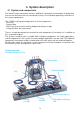
4. System description 4.1 System and components The overall system description contains additional information and examples of application that are not mentioned (or only mentioned in part) in the individual operating instructions of the system components.
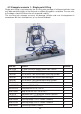
4.2 Example scenario 1 - Single point lifting Single point lifting is carried out by the assisting train manager if rail-bound vehicles have only been derailed slightly at the front and a suitable lifting point is available. The rear axle, or the bogie, should still be on the rails to provide stability. The assisting train manager assesses the damage situation and uses the equipment in accordance with their intended use, or has them distributed. Item No.
4.3 Structure and process - Single point lifting All the hydraulic cylinders are ready for use as soon as they are unpacked. That is to say, the equipment is filled with oil and has been bled of air. All the hydraulic components supplied are accompanied by detailed individual operating instructions, together with this system overview. The user must be familiar with them and must observe them. Drive The drive unit is provided as hydraulic power packs with petrol engines (GC...) and electric motors (PC...).
Hose lines with couplings Only one type of hose is required for the various connection possibilities. All connections are fitted with nipples or sleeves to prevent mix-ups (can be coupled via nipple and sleeve). The hose lines are filled with hydraulic fluid and bled of air in the as-delivered condition. Proceed as follows to connect the hose ends: 1. The gold-coloured coupling nipple on the end of the hose must be connected first.
Control table The CU 2DV control table is set up so that the vehicle to be lifted is in clear view. The distance to the hydraulic cylinder furthest away should be such that the hose length available has adequate reserve. The scope of supply includes 1 m connection hose so that the hydraulic power pack can be connected directly or at a distance using the pair of hose extensions.
Rerailing bridge Various different bridge dimensions are available (see separate operating instructions for LUKAS traversing system), depending on the requirement. You need to take account of the permissible loading with respect to the support distance. If parts of bridges need to be installed/connected, you need to provide packing under the joint areas (see separate operating instructions for LUKAS traversing system). The bridges must be set horizontally, even if the track is over height.
DUO traversing unit The LUKAS traversing unit facilitates complete control of all the components from the control table. The locking pin, also called the anchor cylinder, is a double-acting hydraulic cylinder that is integrated in the DUO traversing unit to hold the position. The hose line on the locking pin is coupled on the control table at the valve with the red control lever and the relevant symbolic marking.
4.4 Example scenario 2 - Two point lifting Two point lifting is carried out by the assisting train manager if he considers the situation of the rail-bound vehicle to be unstable, or if the rerailing concept provides for this. The assisting train manager assesses the damage situation and has the equipment and devices positioned according to their intended purpose. Item No.
4.5 Structure and process - Two point lifting The parts listed in the parts list (table) are matched to specific rail-bound vehicle with regard to the dimensions and weight of the vehicle. The vehicle is lifted up at the lifting points provided (see illustration below) in order to create enough room for the traversing technology. Suitable load carrying equipment can be used for this. On the control table we connect two lifting cylinders HP25/T450 R to the left valve group.
The rerailing bridge is placed under the derailed vehicle and is packed up with wooden beams if necessary. If the length of a single bridge is inadequate, two bridges can be bolted together with the connecting element, thus providing an extension. Here again you need to make sure that enough packing-up is provided. Both rolling carriages are then placed on the bridges and connected together using the two telescopic connecting rods.
The preselection valve is now moved to the left again and the lifting cylinders HP 25/T450 R are fully retracted. To do this both the relevant control levers allocated to the cylinders are pushed forwards at the same time. The two lifting cylinders are then removed from the lifting points and the load is now resting only on the traversing system (see example illustration below). ATTENTION! The operating pressure in the system must be dissipated before uncoupling the hoses.
The holes in the rerailing bridge and the pins on the locking unit are manufactured as a matched pair with regard to the angular inclination. This prevents the lock from coming loose inadvertently. If a single hole pitch is not adequate when traversing the bridge, the traversing cylinder with the locking pin is moved by approx. 1 cm to the centre of the hole. The locking pin is then released using the control lever with the red ball end.
ATTENTION! The operating pressure in the system must be dissipated before uncoupling the hoses. When the rerailing work is complete you must release the operating pressure in the installation/system. Before uncoupling all the hose line, the piston rods need to be retracted into the cylinders and then extended by max. 5 mm. Switch the hydraulic power pack motor off in this position and actuate all the control levers in both directions. You normally hear a pressure release sound (hissing).
5.
Please dispose of all packaging materials and removed items properly. LUKAS Hydraulik GmbH A unit of the IDEX Corporation Tel.: (+49) 0 91 31 / 698 - 0 Fax.: (+49) 0 91 31 / 698 - 394 e-mail: lukas.info@idexcorp.com www.lukas.com Made in GERMANY Rerailing_system_overview_manual_1400000085_en.