
Manual


28
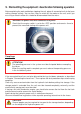
A
B
C
4. Fit the components "A" and "C" back in place in reverse order.
5. Pour the new hydraulic fl uid through the fi ller neck into the tank and close the neck again
with fi ller cap "B".
6. The unit then has to be bled again as described in the Chapter "Commissioning".
Procedure for hydraulic fl uid replacement:
1. Switch the engine off or isolate the electric motor from the mains. Place the power unit
on a slightly elevated base so that the drain plug for the hydraulic fl uid can be easily
reached.
2. Place a suitable collection vessel under the drain screw "A" or the hydraulic oil drain
opening into which it is screwed.
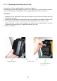
3. Remove the side panel to gain access to the hydraulic tank closure. Open the fi ller cap
"B", remove the drain screw "A" and the sealing ring "C" and let the hydraulic fl uid fl ow
into the prepared collection vessel (see illustration).