
Manual

26
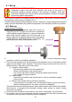
9.3.4 Control valve "simultaneous operation"
Two levers are tted on this valve. Each lever is assigned to one pressure port. The pressure
application of the relevant pressure hose is controlled by turning the relevant lever.
There are 2 switching stages for each lever:
0 = circulation at static pressure (no pressure supplied to the hydraulic hose)
1 = pressure supply to the pressure hose
9.3.5 Controlvalve"triple-owoperation"
Three levers are tted on this valve. Each lever is assigned to one pressure port. The pressure
application of the relevant pressure hose is controlled by turning the relevant lever.
There are 2 switching stages for each lever:
0 = circulation at static pressure (no pressure supplied to the hydraulic hose)
1 = pressure supply to the pressure hose
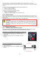
Case 3: Two hose pairs and one rescue device are connected (at connection A):
If two hose pairs are connected and there is only one rescue device at the hose pair of
connection "A", the following instructions are important:
1. The control lever for switch positions must be in position "A".
2. The hydraulic uid supply of the connected rescue equipment and switching to circulation
at static pressure take place by switching the control lever for the outlet valve. ("1" = uid
supply; "0" = circulation at static pressure)
Case 4: Two hose pairs (with quick-disconnect couplings) and one rescue device are
connected (at connection B):
If two hose pairs are connected and a rescue device is only connected at the hose pair of
connection "B", the device works neither in switch position "A" nor in switch position "A+B".
The second hose pair at connection A without a connected rescue device indicates to the
valve that a device is connected at connection A that has to be supplied with maximum
operating pressure. This switches off connection B, which is no longer supplied with hydraulic
uid.
To exclude this possibility, you should either connect a second rescue device or join the
supply and return hoses of the connection that is not used (short-circuiting).
Case 5: Two hose pairs (with mono-couplings) and one rescue device connected (at
connection B):
If two hose pairs are connected and a rescue device is only connected at the hose pair
of connection "B", the device only works in switch position "A+B". This is made possible
by the female mono-coupling halve, which enables an internal uid circulation when not
connected.