Operating instructions for rescue equipment Hydraulic units 175010085 GB Issue 12.2009 replaces 03.
Content Page 1. Hazard classes 4 2. Product safety 5 3. Proper use 9 4. Labelling of the units 9 5. Functional description 10 5.1 General information 10 5.2 Motor variants 10 5.3 Valve variants 11 5.4 Pumps 12 5.5 Frames 13 5.6 Connection to the rescue equipment 14 5.7 Connection options 14 6. Assembly of coupling systems 15 6.1 Mono-couplings 15 6.2 Direct connection 15 6.3 Quick-disconnect couplings 16 6.4 Adapter for direct connection to mono-coupling valve block 16 7.
12. Repairs 30 12.1 General information 30 12.2 Preventive service 31 12.3 Repairs 33 13. Troubleshooting 40 14.
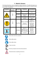
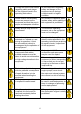
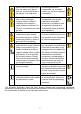
1. Hazard classes We distinguish between various categories of safety instructions. The table below gives you an overview of the assignment of symbols (pictograms) and key words to the specific hazard and possible consequences.
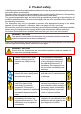
2. Product safety LUKAS products are developed and manufactured in order to guarantee the best performance and quality when used properly. Operator safety is the most important aspect of the product design. Moreover, the operating instructions are intended to ensure LUKAS products are used safely. The generally applicable legal and other binding regulations pertaining to the prevention of accidents and protection of the environment apply and are to be complied with in addition to the operating instructions.
Comply with all the instructions regarding safety and danger on the equipment and in the operating instructions. All the instructions regarding safety and danger on the equipment are to be kept complete and in a legible condition. Please ensure that all safety covers are present on the equipment and that they are in proper and adequate condition.
Keep combustion engines and their fuel away from ignition sources, as otherwise there is the danger of an explosion. All damaged electrical components e.g. scorched cables, etc. are to be replaced immediately! To avoid the danger of fire when using combustion engines, ensure sufficient ventilation and maintain a safety distance of at least 1 m (39.4 in.) to the walls and other screens.
WAR N IN G / D A N GE R / CAUT I O N! The equipment is to be used exclusively for the purpose stated in the operating instructions (see chapter "Proper use"). Any form of use beyond this is not considered proper use. The manufacturer / supplier is not liable for any damages resulting from improper use. The user bears sole responsibility for such use. Observance of the operating instructions and compliance with the inspection and maintenance conditions are covered by the definition of proper use.
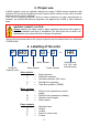
3. Proper use LUKAS hydraulic units are specially designed to supply LUKAS rescue equipment with hydraulic fluid so that this equipment can be used to rescue victims of road, rail or air traffic accidents as well as from buildings. Their use for supplying pressure / fluid to rescue equipment of other manufacturers is possible, yet requires the technical inspection and approval by LUKAS in each individual case.
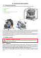
5. Functional description 5.1 General information The main components (see sample illustration) of all LUKAS hydraulic units are: 1 2 3 4 5 6 Fluid reservoir Motor Pump Frame Connecting block with control valve Carrying handle 2 5 4 6 6 3 1 5 3 1 2 1 5 As a general principle on all LUKAS hydraulic units, a hydraulic pump is operated with a motor (combustion engine or electric motor) that feeds the fluid from the reservoir and builds up the pressure.
5.2.2 Gasoline / petrol These hydraulic units are equipped with a combustion engine driven by the fuel "gasoline / petrol". (For specific details, please consult the separate operating instructions of the engine manufacturer!) The engines of type Briggs & Stratton have a main switch, which must be actuated for switching the aggregate on and off. The accelerator cable of these engines does not have to be readjusted and is fixed in the position „ “.
5.3.3 Control valve "automatic operation (ISV valve)" 5.3.4 Control valve "simultaneous operation" 5.3.5 Control valve "triple-flow operation" This valve enables the connection of two pressure hoses and two return hoses. The patented LUKAS ISV valve provides one device at each connecting block with pressure without a manual switching procedure. Changeover between the two pressure hoses is automatic.
5.5 Frames As a general principle, all hydraulic units from the rescue equipment range come with a frame to make them easier to transport. 5.5.1 Standard frame The standard frames vary depending on the type of hydraulic unit. They range from simple handles through to bow-type handles all the way to a frame adapted according to the unit. It therefore cannot be guaranteed that the entire unit can fit inside the exterior dimensions of the frame of standard frames. 5.5.
5.5.4 Frame for rescue sets The frame for rescue sets is specifically designed for the motor / engine and all the components included in a rescue set. In some cases, these frames have additional mounting options or special attachment parts. (For specific information, please contact your authorised LUKAS dealer or LUKAS directly.) 5.5.5 F frames The F frame is currently the largest frame in the LUKAS range.
6. Assembly of coupling systems 6.1 Mono-couplings Only female mono-coupling halves are mounted on the connecting block of the hydraulic unit. The female coupling is screwed into the valve block with a tightening torque of MA = 40 Nm. 6.2 Direct connection On the connecting block of the hydraulic unit, the connection nipple (male) is screwed into the valve block with a tightening torque of MA = 40 Nm. Subsequently, suitable locking elements (e.g.
6.3 Quick-disconnect couplings On the connecting block of the hydraulic unit, the connection nipples are replaced by quickdisconnect couplings to enable connection of hoses equipped with this coupling system. First of all, remove the connection nipples and then screw in the quick-disconnect couplings. The return hose connection (marked in blue) must always be equipped with a female quick-disconnect coupling.
7.
7.1 Coupling the mono-couplings The hydraulic hoses are connected without the risk of confusion via mono-coupling halves (male and female) to the hydraulic pump. Dust protection caps Mono-coupling halve (male) Mono-coupling halve (female) Before coupling, remove dust protection caps, then connect male and female, and turn the locking sleeve of the female to direction "1" until the locking sleeve locks into place. The connection is now in place and secure.
7.2 Coupling the quick-disconnect couplings The equipment is connected to the hydraulic pump via quick-disconnect coupling halves (male and female). X Y Before coupling, remove the dust protection caps, then pull back and hold the locking sleeve of the female coupling (position X). Connect the nipple and female coupling and let go of the locking sleeve. To conclude, turn the locking sleeve into position Y. The connection is now in place and secure. Uncouple in reverse order.
7.3 Direct connection REMARK: In order to be able to mount the hoses directly onto the connecting block, adapters or connection nipples have to be screwed into the valve block beforehand. The hydraulic hoses are screw-connected to the connecting block of the hydraulic unit. Screw-in sleeves or adapters are mounted in the valve block. The hoses are secured directly onto these screw-in sleeves or adapters by means of union nuts.
8.1 Set-up WARNING / DANGER / CAUTION! Combustion engine units and most electrical units must not be used in a potentially explosive situation (danger of the formation of sparks). Units with combustion engines must not be used in enclosed spaces, as there is a danger of poisoning and/or asphyxiation! The unit is to be set up in a suitable location (safe location / flat surface / sufficient distance from vehicles, loads, sources of ignition, etc.). LUKAS units work perfectly at an angle of up to 30°.
9. Operation CAUTION! As a general principle, before starting up the motor, the hydraulic unit is to be switched to circulation at static pressure (i.e. the outlet valves are to be opened, for example). Only in this way is it possible to start the unit without a hydraulic load. 9.1 Starting the motors 9.1.1 Gasoline / petrol and diesel engines Before starting the combustion engines, check that the fuel tank is full and that the engine oil level is within the permitted tolerances.
An electric starter is available from the LUKAS range of accessories for some units. (For specific details, please consult the LUKAS range of accessories or contact your LUKAS dealer). On these units, after checking the fluid levels, proceed as follows: 1. Switch to "START ENGINE" 2. Turn the ignition key clockwise. Charge the accumulator of the electric starter: 1. Switch to "CHARGE BATTERY" 2. Connect the supplied charger to the mounted socket. 10.1.
Flow chart for stopping Honda motors, unit type 620: 1. Set the ON / OFF switch to the OFF position. 2. When the engine has come to a standstill, close the fuel tap. Please consult the separate operating instructions of the motor manufacturer for the precise procedure for stopping combustion engines! WARNING / CAUTION! Never touch the hot motor / engine parts: this could result in severe burns! 9.2.
9.3.3 Control valve "automatic operation (ISV valve)" There is no direct control option for this valve, since the pressure application is controlled automatically. Nonetheless, the unit also has 2 levers or switches. The top lever controls whether or not one device (switching position "A") or two devices (switching position “A + B”) should be operated. The side switch is to control the outlet valve, which means that in switch position "0" the unit is switched to circulation at static pressure.
Case 3: Two hose pairs and one rescue device are connected (at connection A): If two hose pairs are connected and there is only one rescue device at the hose pair of connection "A", the following instructions are important: 1. The control lever for switch positions must be in position "A". 2. The hydraulic fluid supply of the connected rescue equipment and switching to circulation at static pressure take place by switching the control lever for the outlet valve.
10. Dismantling the equipment / deactivation following operation Once work has been completed, all connected equipment is to be reset to its base position before the unit is shut down. You can now stop the motor of the unit / switch it off and, if using an electric motor (without accumulator), disconnect it from the mains supply. Mono-couplings: If the connected hose assemblies have to be dismantled during shut-down, decouple as described in chapter "Coupling the mono-couplings".
11. Maintenance and service The hydraulic units are subject to very high mechanical loads. A visual inspection is therefore to be carried out after every use: however, at least one visual inspection is to be carried out every six months. This reveals wear and tear in good time; punctual replacement of these wearing parts prevents damage to the equipment.
11.2 Hydraulic units with combustion engine Visual inspection Hydraulic units • Check that all hydraulic connections are tightened, • General tightness, no leakage (the hot oils do not have any influence on the function) • Is there any damage apparent on the motor, valve blocks or on the casing? • Existence and stability of carrying frame • Are type plate, all activation plates, signs, identification marks and warning labels are present and legible? • Are all covers (e.g.
Function test • No suspicious noises • Test for maximum load (Recommendation: use the LUKAS test kit, including testing instructions, for the function test). 12. Repairs 12.1 General information Servicing may only be carried out by the manufacturer or personnel trained by the manufacturer and by authorised LUKAS dealers.
12.2 Preventive service 12.2.1 Care regulations The exterior of the equipment is to be cleaned from time to time in order to protect it from external corrosion. Oil is to be applied to the metallic surfaces. 12.2.2 Function and load test If there is any doubt regarding the safety or reliability of the equipment, a function and load test must also be performed. LUKAS offers appropriate test equipment. 12.2.3 Replacing the hydraulic fluid - After approx.
3. The fastening screws of the hydraulic fluid reservoir must then be loosened. 4. Remove the reservoir and the seal below it. 5. Free the entire reservoir of dirt using a smooth cloth. 6. When fitting the reservoir, replace the reservoir seal and tighten the fastening screws (tightening torque, see spare parts list or separate instructions for your unit in the chapter entitled "Technical data".). 7. Also replace the seal ring of the drain plug and fit it as specified in the spare parts list. 8.
12.3 Repairs When carrying out permitted repairs, please observe the relevant spare parts lists with the remarks and drawings they contain. Should there be any uncertainties regarding the repairs, please contact your authorised LUKAS dealer or LUKAS Customer Service. CAUTION! Valve blocks and motors / engines may only be replaced by qualified personnel (e.g. equipment supervisor) taking account of all applicable standards, regulations and laws. 12.3.
12.3.2 Mono-couplings The mono-couplings on the connection hoses on the equipment must be replaced in the event of: - external damage - the locking device not working - hydraulic fluid continually leaking in a coupled/uncoupled state. WARNING / DANGER / CAUTION! Never repair couplings: they are to be replaced by original LUKAS parts! Procedure when mounted on hoses: 1. Remove the cover from the couplings. 2. Loosen the union nuts of the hose assembly and remove the coupling. 3.
12.3.3 Quick-disconnect couplings The quick-disconnect couplings must be replaced in the event of: - external damage - the locking device not working - hydraulic fluid continually leaking in a coupled/uncoupled state. WARNING / DANGER / CAUTION! Never repair couplings: they are to be replaced by original LUKAS parts! Procedure when mounted on hoses: 1. Loosen the union nut of the hose assembly and remove the coupling. 2.
CAUTION with (quick-disconnect-system)! As the case may be, make sure that reservoir port 'T' or 'T1' of the unit is always equipped with a female quick-disconnect coupling. On the other hand, the supply ports must be equipped with a male quickdisconnect coupling. 12.3.6 Replacing the valve blocks Replace the valve blocks if they are leaky or defective and direct repair of the valve block by a dealer or LUKAS is no longer possible.
7. Clean the fastening point and the connection nipple for the piping using a non-fibrous cloth. 8. Screw the connection nipple for the piping and the return pipe into the valve block and tighten. 9. Apply seal using sealant. 10. Place a new seal on the fastening point and bolt the new valve block to the unit once again. Please consult the spare parts lists for the necessary torques.
5. Position the new valve block on the connection flange, making sure you do not move or damage the O-rings. 6. Now screw on the fastening screws of the valve block and tighten. Please consult the spare parts lists for the necessary torques. 7. Vent the unit once the repairs are complete. 12.3.7 Replacing the engines / motors Replace the engines / motors if they are defective and direct repair of the valve block by a dealer or the manufacturer is no longer possible.
7. Perform a function test with the hydraulic unit (as described in the chapter entitled "Maintenance and service"). (Recommendation: use the LUKAS test kit, including testing instructions, for the function test). 12.3.8 Labels All damaged and/or illegible labels (safety notices, type plate, etc.) must be renewed. Procedure: 1. Remove damaged and/or illegible labels. 2. Clean the surfaces using acetone. 3. Attach new labels. Make sure that the labels are attached in the right position.
13. Troubleshooting In the case of defects which directly affect the motor / engine, please consult the separate operating instructions of the motor / engine manufacturer.
Trouble The connected rescue equipment does not move on activation of the valve, or moves only very slowly or unevenly.
Trouble Fluid leaks from the hydraulic fluid reservoir (especially from the filler screw) Cause Return of the hydraulic fluid from the rescue device exceeds the reservoir’s maximum quantity when filled.
Trouble With quick-disconnect coupling system: Leak in the coupling (male) Cause Safety valve reacted With quick-disconnect coupling system: Leak in the coupling (female) Female coupling defective Hydraulic fluid leak on the hoses or the connections Damage on the surface of the hydraulic hoses Leak, possible damage Replace hoses Mechanical damage or contact with aggressive agents Replace hoses Coupling (male) defective Solution After pressure release, there is no more leakage.
14.
WARNING / DANGER / CAUTION! Before connecting equipment, make sure that all the components used are suitable for the maximum operating pressure of the hydraulic unit! In cases of doubt, you must consult LUKAS directly before connecting the equipment! Please dispose all packaging materials and dismantled parts properly. LUKAS Hydraulik GmbH Tel.: (+49) 0 91 31 / 698 - 0 Fax.: (+49) 0 91 31 / 698 - 394 e-mail: lukas.info@idexcorp.com Made in GERMANY Aggregate_BA_GB_175010085_1209.