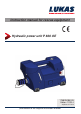
Instruction manual for rescue equipment Hydraulic power unit P 600 OE 175825085 EN Edition 11.2014 replaces 01.
Contents Page 1. 2. 3. 4. Danger classes Product safety Proper use Functional description 4.1 Description 4.2 Structure of P600OE 5. Connecting the hoses / devices 6. Set-up and start-up 6.1 Installation 6.2 Commissioning 7. Operation 7.1 Operating the P600OE 7.2 Safety instructions 8. Dismantling the equipment / deactivation following operation 9. Tests 9.1 General information 9.2 Testing the devices 10. Maintenance and repair 10.1 General information 10.2 Preventive maintenance 10.
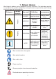
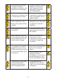
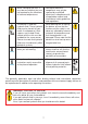
1. Danger classes We distinguish between various categories of safety instructions. The table below provides an overview of the symbols (pictograms) and signal words assigned to the specific danger and also the possible consequences.
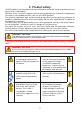
2. Product safety LUKAS products are developed and manufactured to guarantee the best performance and quality when used properly. Operator safety is the most important aspect of the product design. Moreover, the operating instructions are intended to aid the safe use of LUKAS products. The generally applicable legal and other binding regulations pertaining to the prevention of accidents and protection of the environment apply and are to be complied with in addition to the operating instructions.
In the event of malfunctions, shut down the device immediately and make it safe. Repair the fault immediately. Do not carry out any changes (additions or conversions) to the equipment without obtaining the approval of LUKAS beforehand. Observe all safety and danger information on the device and in the operating instructions. All safety and danger information on the device must always be complete and in a legible condition.
Damage to electrical components may only be repaired by a qualified electrician in compliance with all applicable national and international safety guidelines and regulations. When working with or storing the device, ensure that the function and the safety is not adversely affected by external extremes of temperature and that the equipment is not damaged. Please note that the device can also heat up over a long period of use.
WAR N IN G / C A U TION / AT T E NT I O N! The device is intended exclusively for the purpose stated in the operating instructions (see chapter "Proper Use"). Any other use is not in accordance with its designated use. The manufacturer/supplier cannot be held liable for any damage resulting from such use. The risk of such misuse lies entirely with the user. Proper use includes observance of the operating instructions and compliance with the inspection and maintenance conditions.
You can order replacement parts and accessories for LUKAS equipment from your authorised LUKAS dealer! 4. Functional description 4.1 Description The P600OE is a compact lightweight electrically driven hydraulic pump. It is designed for supplying hydraulic power to a double-acting LUKAS rescue unit. Their use for supplying pressure / fluid to rescue equipment of other manufacturers is possible, yet requires the technical inspection and approval by LUKAS in each individual case.
In addition, the P600OE is fitted with LED lighting as standard in order to make working under reduced visibility conditions easier. The light-emitting diodes attached on the connection side light up the coupling area. The main switch has also been provided with a light, so that you can see at a glance whether the device is switched on. The hydraulic tank is also lit. This allows you to see the fill level at any time if the lighting conditions are poor.
4.
5. Connecting the hoses / devices CAUTION! When connecting the hose assemblies / units, always ensure that the connection components are not soiled.
NOTE: Couple together only when in ECO mode, or when the P600OE is switched off! For dust protection, the supplied dust protection caps must be refitted. Fitting the dust protection caps: The dust protection caps "A" have two external grooves "B". The dust protection caps must be inserted in the female coupling in such a way that the grooves can be guided over the pins "C". Screw in the dust protection caps to the limit stop to fix in the female couplings.
6. Set-up and start-up 6.1 Installation WARNING / CAUTION / ATTENTION! The LUKAS Mini electric pump is not explosion protected! When using the equipment in explosion risk areas you must make sure that operation of the unit does not trigger an explosion! The unit is to be set up in a suitable location (safe location / flat surface / sufficient distance from vehicles, loads, sources of ignition, etc.). LUKAS units work perfectly at an angle of up to 20°.
Maximum fill level Minimum fill level The hydraulic fluid level should never fall below this level, even when the unit is running, since otherwise the pump will be damaged! 3. If necessary, fill with hydraulic fluid up to the maximum level. Filling with hydraulic fluid is carried out as possible: a) Open the filler cover completely. Slight resistance must be overcome to open it. This is designed to prevent inadvertent opening of the cover.
The filler cover can also be removed completely to make filling easier. To do this open the filler cover by approx. 35° and pull the cover off towards the coupling. Do not use force since this could damage the cover. 1. 2. NOTE: Do not fill up to the maximum mark because otherwise hydraulic fluid could come out of the filler cap when running. b) Open the filler cap on the fluid tank. c) Fill with hydraulic fluid up to the maximum mark.
4. Now insert the battery or the mains adapter into the unit (if not already fitted). The mains adapter must then be connected to the power supply. 5. The hydraulic unit must now be bled. This takes place fully automatically on the P600OE. To carry out bleeding you just have to switch the hydraulic pump on at the main switch and let it run for two to three minutes without having a unit connected to it. The filler cap is also fitted with a vent which automatically bleeds the tank when the pump is running. 6.
7.2 Safety instructions World-wide, safety guidelines pertaining to the specific country must be observed and complied with. In the Federal Republic of Germany, regular safety inspections according to the legal accident insurance regulations (GUV - Gesetzliche Unfallversicherung) are mandatory.
8. Dismantling the equipment / deactivation following operation Procedure: 1. When the work is completed, the connected units must be returned to the starting position. This should mean that the hydraulic tank on the P600OE has the starting volume of hydraulic fluid. 2. Then switch off the device at the main switch. 3. Separate the connected unit from the hydraulic unit. 4. After each use, the pump must be cleaned externally and wiped down with a damp cloth.
9. Tests 9.1 General points The P600OE is subject to very high levels of mechanical loading as a result of the high operating pressure. A visual inspection must therefore be carried out after every use and at least one visual inspection must be carried out every six months. These inspections enable the early detection of wear and tear, which means that punctual replacement of these wearing parts prevents damage.
If the noises and suspicions referred to above arise several times in a month, or if maximum pressure cannot be achieved during the function test, you need to contact LUKAS customer service immediately. The contact details are given in the Chapter "Fault analysis".
10. Maintenance and repair 10.1 General points NOTE: Always register your tool on the LUKAS Hydraulik GmbH internet site. Only then are you entitled to the extended guarantee. Because of the complex construction and the high hydraulic pressure, repair work must only be carried out by the unit manufacturer or by personnel specially trained by the unit manufacturer and by authorised LUKAS dealers. For these reasons, only simple maintenance work is listed in this manual.
10.3 Changing the hydraulic fluid After approx. 200 deployments, but after three years at the latest, replace the hydraulic fluid. The fluid should be replaced when it is warmed up. When replacing the hydraulic fluid, the pump must be deactivated and the battery or the mains unit must be removed from the connection slot. The old hydraulic fluid must be disposed of properly. Procedure: 1. Open the filler cover. Removal of the filler cover will make the subsequent tasks easier. 1. 2. 2.
3. Pour the hydraulic fluid into a suitable collection vessel. 4. Place the P600OE on level, flat ground and fill up to the maximum mark. 5. Then close the tank again with the filler cap and insert the battery into the connection slot or connect the pump to the power supply. 6. Switch the pump on and let it run for approx. 2-3 minutes. This bleeds the pump. 7. Check the level in the tank again and top up if necessary. 8. Then fit the filler cover back in place and close off the tank access on the unit.
10.4 Checking the filters The air inlet filter should be checked at least once a year. The filter can be checked from the outside if the mains unit (or battery) is removed (see illustrations below). If the filter is severely contaminated, it will need to be replaced. At the same time, the filters in the air exhaust must be replaced. To do this, the housing must be opened up by trained personnel and the filter replaced (see also spare parts list). Procedure: 1. Tilt the P600OE as shown in the illustrations.
11. Troubleshooting Fault Check Cause Solution The initiation sequence period of 3 seconds is not allowed to be carried out Switch the pump off and on again. Use the rescue unit only after the initiation sequence has been fully carried out. Flashing light in the on/off switch goes to permanent light (see also Paragraph 7.
Fault P600OE stops during operation Electric motor not providing full power Check Battery or mains unit positioned correctly in the connection slot and locked in position Check connection of mains unit Check battery charge status Cause Solution Battery or mains unit not inserted properly Remove the battery or mains unit from the pump and re-insert.
Fault Check Pump does not switch to WORKING mode after actuating the connected rescue unit Solution Switch unit off, then switch it on again and wait for initiation Control valve of connected rescue unit actuated too slowly or too tentatively. Actuate the control valve again. Rescue unit not connected correctly (locking sleeve on the coupling not fully rotated to "1") Turn the locking sleeve on the coupling fully to the end position "1".
Fault Check The connected rescue equipment does not move on activation of the valve, or moves only very slowly or unevenly. Connect a different unit and check whether it works when actuated Leaks from pump body itself Connected rescue device does not reach its final position Check hydraulic fluid volume in hydraulic reservoir Cause Solution The previously connected unit is defective.
Fault Check Connected rescue device does not reach its specific performance data During function test: A pressure gauge installed between the rescue equipment and the hydraulic power pack does not indicate the maximum operating pressure of the equipment.
Fault Cause Solution Connected unit not in base position yet and fluid coming out of filler cap? Return of the hydraulic fluid from the rescue device exceeds the reservoir’s maximum quantity when filled.
If you cannot rectify the malfunctions, inform an authorised LUKAS dealer or the LUKAS customer service department immediately! The address of the LUKAS Customer Service Department is: LUKAS Hydraulik GmbH Weinstraße 39, Erlangen, 91058 Germany Phone: (+49) 09131 / 698 - 348 Fax.: (+49) 09131 / 698 - 353 12. Technical data Since all values are subject to tolerances, minor differences may occur between the data on your equipment and the data in the following tables.
12.1 P600OE Type P 600 OE 81-53-10 (175825000) Item number Dimensions (excluding battery) LxWxH Motor power rating [mm] 460 x 182 x 257 [in.] 18.11 x 7.17 x 10.12 [kW] 1.0 [HP] 1.34 [MPa]3) Max. operating pressure (HD)1) Volume flow (HD)1) 70 [psi.] 10000 [l/min] 0.45 [gal.-US/min] 0.12 Max. operating pressure (ND)2) [MPa]3) 14 [psi.] 2 Volume flow (ND)2) [l/min] 2.4 [gal.-US/min] 0.64 [l] 1.5 [gal.-US] 0.40 [l] 1.2 [gal.-US] 0.32 [kg] 8.3 [lbs.] 18.3 [kg] 9.
12.1 P600OE Power consumption at full load [A] 40 Max. power consumption 230VAC (with eDraulic Power Supply 230 VAC) [A] 7 Starting current 230VAC (with eDraulic Power Supply 230 VAC) [A] 16 Max. power consumption 110VAC (with eDraulic Power Supply 110 VAC) [A] 10 Starting current 110VAC (with eDraulic Power Supply 110 VAC) [A] 22 Protection category IP54 Max. permissible hose length 1) HD = High-pressure 2) ND = Low pressure 34 [m] 10 [ft.] 32.
12.2 Noise emissions (based on the EN ISO 3744 standard) Used power source Lithium-ion battery Power supply Idling (measured at a distance of 1 m) [dB(A)] 54 54 Full load (measured at a distance of 1 m) [dB(A)] 71 71 Idling (measured at a distance of 4 m) [dB(A)] 53 53 Full load (measured at a distance of 4 m) [dB(A)] 67 67 12.
13.
14. Accessories 14.1 Batteries Only LUKAS lithium-ion rechargeable batteries may be used to operate the P600OE. These guarantee optimum performance and maximise the operating time of the units. Charging state indicator Query button NOTE: Pay strict attention to the separate operating instructions for the battery. 14.2 Battery charger Only the "eDRAULIC Power Pack Charger" may be used for the lithium/ion batteries. NOTE: Pay strict attention to the separate operating instructions for the battery charger.
14.3 Power supply The P600OE has a unique power supply with integrated electronics, allowing the devices to be operated for an almost unlimited time by connecting them to an external power source. The power supply converts the voltage of the external power source in such a way that it may be used instead of a battery. Cable Filter Adapter Cable Mains plug Structure: There is an adapter on one side of the power supply which can be simply inserted into the connection slot of the devices and locked.
15. Instructions regarding disposal Please properly dispose of all packing materials and removed parts. Electrical equipment, accessories and packaging should always be disposed of in an environmentally compatible way.
16.
LUKAS Hydraulik GmbH A unit of the IDEX Corporation Weinstraße 39, Erlangen, 91058 Germany Phone: (+49) 0 91 31 / 698 - 0 Fax.: (+49) 0 91 31 / 698 - 394 e-mail: lukas.info@idexcorp.com www.lukas.com Made in GERMANY P600OE_manual_175825085_en.