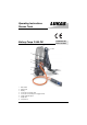
Operating Instructions Rescue Tools 115001085 GB Issue 10.
Contents page 1 Basic Operation and designated Use of the Machine 3 2 Organizational Methods 3 3 General Safety Instructions 3 4 Instructions for Maintenance and Service 4 5 Safety Instructions for Hydraulic Hoses 5 6 Intended Use 7 7 Description 7 8 Commissioning 9 9 Operation 10 10 Maintenance 13 11 Problems / Trouble Shooting 15 12 Repair 16 13 Battery 16 14 Technical Data 17 2
1 Basic operation and designated use of the machine 1.1 The machine has been built in accordance with state-of-the-art standards and the recognized safety rules. Nevertheless, its use may constitute a risk to life and limb of the user or of third parties, or cause damage to the machine and to other material property. 1.
3.3 Before transporting the machine always check that the accessories have been safely stowed away. 3.4 Make sure that there is enough lighting during work. 3.5 Avoid any operation that might be a risk to machine stability. 3.6 Check the machine at least after every operation for obvious damage and defects. Report any changes (incl. changes in the machine’s working behaviour) to the competent organization /person immediately. If necessary, stop the machine immediately and lock it.
4.8 Should you observe a loss of speed of the rescue tool during operation the battery must be recharged. Do not continue with the operation until the motor stops. Otherwise there is the risk of the battery becoming deep discharged which would reduce its lifetime.
5.
5.5 Inspection and replacement intervals of hoses - After each operation the hoses have to be checked for external damages, cracks, kinks and bubbles! - The operator has to replace the hoses in appropriate period of times, even if there are no visible security defects on the hoses. - The hoses have to be replaced 10 years as from date of manufacture at the latest (see marking on the hose)! Hoses are subject to a natural aging even if they are stored correctly.
7.2 Drive unit with pump and motor 7.2.1 Motor A 24V DC electric motor (2) with a power of 480 W is used for driving the hydraulic pump. 7.2.2 Hydraulic pump with valves The hydraulic pressure is produced by a LUKAS radial piston pump (1) with: - low pressure circuit (up to 8 MPa) = LP - high pressure circuit (up to 63 MPa) = HP (10 bar = 1 MPa) Necessary valves are also integrated in the pump unit: - switch-over from low to high pressure is made automatically by a switch-over valve (3) - the max.
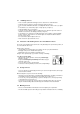
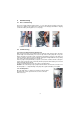
8 Commissioning 8.1 First commissioning Prior to first commissioning the battery (item 3, see cover page) must be charged. Connect the charger to a suitable power supply. Connect the plug on the charging cable with the charging socket in the battery housing (item 4, see cover page) contact pins contact ring with holes picture 5 8.2 picture 6 picture 7 Commissioning 8.2.
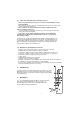
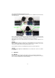
8.2.3 Connection between pump and rescue tool The hydraulic hoses are connected free of confusion via mono-coupling halves (male and female) to the hydraulic pump. mono-coupling halve (male) mono-coupling halve (female) Before coupling, remove dust protection caps, then connect male and female, and turn the locking sleeve of the female to direction „1“ until the locking sleeve locks into place. The connection is now in place and secure. Decoupling is by turning the locking sleeve to direction „0“.
9.2 Function of the main switch With the main switch (see picture 9) the pump can be switched on or off. In the ”on” position the main switch is illuminated. To prevent damage of the pump unit through voltage peaks a circuit breaker is integrated into the main switch. When activated the circuit breaker would set the main switch automatically to the ”off” position. As soon as the voltage peak is over the pump can be switched on again. 9.
9.8 Succesive operation of several LUKAS rescue tools Depending on the rescue situation it might be necessary to employ the pump for a second or third rescue tool (of course one after another). In such cases observe the following: Prior to connection of a second tool it must be made sure that the first tool has been fully closed/retracted ! Of course, the second tool must also be fully closed prior to connection of a third one and so on.
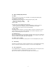
12.2 12.3 13.1 12.1 Bild 14 12.4 Bild 12 Bild 13 9.10 General remark When the connected rescue tool is not needed for a longer period of time, open the dump valve (see picture 8) and switch the pump off so as to save battery capacity. 10 Maintenance 10.
For checking of the hydraulic oil level proceed as follows: 1) 2) 3) 4) 5) 147 Remove the hood on top of the pump unit by opening the 8 allen screws on the bottom end of the hood. Remove the yellow filler screw on top of the oil reservoir. Push the diaphragm downwards until oil is coming out of the filler screw so as to make sure that no air remains in the tank and lock the tank with the filler screw. For checking the correct filling volume adjust the upper part of the oil tank to a horizontal position.
11 Problems / trouble shooting Index: P = problem S = symptom C = check P: pump fails to deliver oil S: rescue tool doesn’t move when the star grip is turned C: hoses and quick couplers properly connected ? Battery properly charged ? -> After adding or changing hydraulic oil the pump must be vented (see 10.3) -> Is the red light on the charge indication panel on ? -> Recharge the battery.
12 Repair For all repairs only genuine LUKAS spare parts as listed in the spare parts list may be used, since it is absolutely necessary to consider for this purpose spezial tools, safety aspects and checks that might be required (see chapter 4). 13 Battery 13.1 The P 600 OB is supplied complete with a CP-100 9 Ah battery pack. 13.2 Special safety instructions for the battery: The CP-100 Pack 9 Ah includes a lead-acid battery which is fully sealed.
14 Technical data 14.1 Pump unit Voltage Current max. Motor power max. Protection class Hydraulic oil filling Usable oil quantity Oil delivery low pressure Oil delivery high pressure Dimensions (h x w x d) Weight (incl. oil filling) Temperature range Working position 14.2 Battery 24 VDC 20 A 480 W IP 12 1.6 l 1.2 l 1.33 l/min 0.33 l/min 570 x 179 x 174 mm 18.
© Copyright 2007 LUKAS Hydraulik GmbH LUKAS Hydraulik GmbH A Unit of IDEX Corporation Weinstraße 39, 91058 Erlangen Postfach 2560, 91013 Erlangen Germany Telefon +49(0)9131/698-0 • Telefax +49(0)9131/698-394 E-mail: lukas.info@idexcorp.com P600OB_BA_GB_115001085.