Operating instructions Rerailing Equipment DUO Traversing System 84072058485 GB Edition 07.2009 replaces 12.
Content Page 1. Hazard classes 4 2. Product safety 5 3. Proper use 8 4. Functions and performance 9 4.1 Description 9 4.2 Hydraulic supply of jacks 10 5. Connection of hydraulic devices 10 5.1 Basic information 10 5.2 Coupling the quick-disconnect couplings 6. Operation 11 12 6.1 Setting up the DUO traversing system 12 6.2 Start-up 25 6.3 Control of the DUO traverse jack with anchor pin 26 6.4 Control of the DUO traverse jack with anchor jack 28 7.
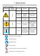
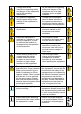
1. Hazard classes We distinguish between various categories of safety instructions. The table below gives you an overview of the assignment of symbols (pictograms) and key words to the specific hazard and possible consequences.
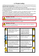
2. Product safety LUKAS products are developed and manufactured in order to guarantee the best performance and quality when used properly. Operator safety is the most important aspect of the product design. Moreover, the operating instructions are intended to ensure LUKAS products are used safely.
Comply with all the instructions regarding safety and danger on the equipment and in the operating instructions. Any method of operation which impairs safety and/or stability of the equipment is prohibited. All the instructions regarding safety and danger on the equipment are to be kept complete and in a legible condition. Comply with all specified dates or dates specified in the operating instructions pertaining to regular checks / inspections of the equipment. Safety devices may never be deactivated.
The generally applicable, legal and other binding national and international regulations pertaining to the prevention of accidents and protection of the environment apply and are to be implemented in addition to the operating instructions. WAR N IN G / D A N GE R / CAUT I O N! The equipment is to be used exclusively for the purpose stated in the operating instructions (see chapter "Proper use"). Any form of use beyond this is not considered proper use.
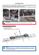
3. Proper use The components of the LUKAS DUO traversing unit are specially designed for rerailing technology. In the event of derailments, the traversing unit is used to raise rail vehicles, move them across the rails, thus allowing the vehicles to be rerailed. A range of accessories such as base plates, stacking sets, etc. is available for specific applications. CAUTION! To minimise the risk to the environment, remedy leaks as soon as possible.
4. Functions and performance 4.1 Description 4.1.1 Rerailing bridge The rerailing bridge is placed across the rails and acts as the base and traverse support for the LUKAS roller carriages and the LUKAS traverse jacks. If one bridge is not long enough, a second bridge can be bolted on by means of connecting elements. The anchor pin or the integrated anchor jack of the traverse jack can be fixed in the openings at the top of the rerailing bridge.
4.2 Hydraulic supply of jacks Only LUKAS motor pumps or suitable LUKAS hand pumps may be used to drive the equipment. If an other-make pump assembly or hand pump is used, it is necessary to make sure that it is designed in accordance with LUKAS specifications otherwise hazardous situations could occur for which LUKAS cannot be held responsible. Particular care must be taken to ensure that the maximum permissible operating pressure of the connected LUKAS devices is not exceeded.
5.2 Coupling the quick-disconnect couplings The device connects to the hydraulic pump by means of individually coded quick-connect coupling halves (plug and socket). X Before coupling, remove the dust protection caps, then pull back and hold the locking sleeve of the female coupling (position X). Connect the nipple and female coupling and let go of the locking sleeve. To conclude, turn the locking sleeve into position Y. The connection is now in place and secure. Uncouple in reverse order.
6. Operation 6.1 Setting up the DUO traversing system 6.1.1 General information The DUO traversing system consists of several individual components. By correspondingly configuring the individual components, several different complete systems can be built up. While not all individual components are required for some of these complete systems, you may need several of the individual components to make up other systems.
In the majority of cases it is not possible to rest the load over the entire surface of the jack piston. We therefore recommend using suitable piston guard plates otherwise the piston rod or jack may be damaged. A convex piston guard plate evenly distributes the load over the surface of the piston. Load Load RIGHT WRONG If several jacks/roller carriages are used simultaneously, the load should be distributed as evenly as possible over all jacks/roller carriages.
- To avoid damaging the piston and to ensure safe force application, never use jacks without a piston guard plate CAUTION! Use an additional non-slip base between the piston guard plate and the load to be lifted as there may also be a greasy film at the contact point on the load! - Make sure that the load is applied centred on to the piston rod. 6.1.3 Setting up the rerailing bridges The bridge is placed across the tracks and carefully supported by wooden planks.
- The maximum load of the bridge connecting elements (optional) is not exceeded: Bridge height Support width Max. load [mm] [in.] 140 [m] [ft.] 1 [kN] [lb] 200 3.28 44,964 5.51 184 1 300 7.24 3.28 67,446 - The bridge is horizontally aligned: The angle of the bridge may not exceed 3°. If one bridge is not long enough, a second bridge can be bolted on by means of connecting elements.
6.1.5 Setting up the hydraulic jacks on the roller carriage The hydraulic jacks are placed in the centre of the upper support plate on the roller carriage if they are to be moved together with the raised load (see illustration below). DANGER / CAUTION! Take care when moving a load raised by a hydraulic jack (mounted on the roller carriage) to ensure that the load cannot tilt while traversing.
6.1.6 Setting up the traverse jacks with fixed anchor pin Fit the traverse jack with the fixed anchor pin in one of the matching mounting points in the rerailing bridge and attach the piston rod head in the centre retainer on the roller carriage (see illustration below). You may have to move the roller carriage a little in order to attach the jack head.
6.1.7 Setting up the traverse jack with anchor jack Fit the traverse jack with the head of the anchor plate in one of the matching mounting points in the rerailing bridge. For this purpose you will have to pull the slide plate on the back end of the traverse jack up a little. Then attach the piston head of the traverse jack in the centre retainer on the roller carriage (see illustration below). You may have to move the roller carriage a little in order to attach the jack head.
Now pull up the slide plate as far as it will go and attach the guide plates on the right and left of the traverse jack. Slide the attached guide plates in the direction of the jack head and push the slide plate down again. The traverse jack is now secured on the rerailing bridge and cannot shift to the side or lift.
6.1.8 Setting up and adjusting the distance bars The distance between the load lifting points must be set exactly with the distance bars. For this reason they come with a rough and fine adjustment option. Rough adjustment of the distance bars: 1. Pull out the lock pin. 2. The coupling bar can now be pulled out to roughly set the distance between the roller carriages. The hole in the coupling bar must be aligned with the corresponding hole in the tube. 3.
Fine adjustment of the distance bars: Fine adjustment takes place at the other end of the tube. Insert a metal rod (ø8 mm) or similar tool in the hole in the adjusting pin and unscrew it (turn in anticlockwise direction) until the required size is reached. For the fine adjustment, the adjusting pin can be unscrewed by a maximum of 80 mm. Connecting two roller carriages: Two distance bars must always be used to connect two roller carriages. These two distance bars must be set to the same length.
NOTE: If the traverse jack is to be used between the two roller carriages, the distance bars should be fitted after setting up the traverse jack. 6.1.9 Examples of traversing systems DANGER / CAUTION! If there are doubts concerning the set-up of your traversing system a correspondingly trained safety technician or LUKAS should be contacted directly before start-up. NOTE: There are two methods of setting up the traverse jack in combination with two roller carriages: 1.
Several examples of setting up traversing systems are illustrated in the following: 1. Traversing system with one roller carriage and separate load lifting system (recommended method) Required components: - Controlled hydraulic supply (e.g. hydraulic unit with control valve) - Separate load lifting system (e.g. hydraulic jack with accessories) - Rerailing bridge - 1 roller carriage - 1 traverse jack - Support material (e.g. hardwood blocks) 2.
3. Traversing system with one roller carriage and mounted hydraulic jack Required components: - Controlled hydraulic supply (e.g. hydraulic unit with control valve) - Rerailing bridge - 1 roller carriage - 1 traverse jack - 1 hydraulic jack - Support material (e.g. hardwood blocks) 4. Traversing system with two roller carriages and mounted hydraulic jacks Required components: - Controlled hydraulic supply (e.g.
6.2 Start-up CAUTION! During start-up, observe all information and instructions in the separate operating instructions for the other components of your rerailing system. Preparations before start-up: Before start-up, all components must be visually inspected for damage and leaks. Damaged components must not be used and must be exchanged. Hydraulic components must be bled before start-up takes place.
DANGER / CAUTION! Make sure that nobody is present in the danger zone. The rerailing system is now ready to use! 6.
9. Lower the vehicle with the separate load lifting system. NOTE: If the traversing range does not extend far enough, after shifting the vehicle for the first time (steps 1 to 9) you will have to build up the entire traversing system once again at the new position of the vehicle. When rebuilding the traversing system make sure that all the prerequisites defined under "Setting up the DUO traversing system" are met! You can now repeat the procedure (1 to 9). 10.
7. Finally, dismantle the components of the traversing system. 6.4 Control of the DUO traverse jack with anchor jack DANGER / CAUTION! The vehicle to be rerailed must be secure according to instructions to prevent it rolling, slipping and tipping! 6.4.1 Traversing with external load lifting system (recommended method): Procedure: 1. Set up the rerailing system as described under "Setting up the DUO traversing system" and in the separate operating instructions of the other components used. 2.
11. Points 9 and 10 can be repeated as often as necessary. NOTE: The traversing range is only limited by the length of the rerailing bridge. DANGER / CAUTION! When shifting several times make sure that the roller carriages are not pushed from the rerailing bridge! 12. Move the separate load lifting system such that you can again safely lift the vehicle to be rerailed. The vehicle must still remain secured to prevent it rolling, slipping and tipping! 13.
DANGER / CAUTION! When shifting several times make sure that the roller carriages are not pushed from the rerailing bridge! 9. Lower the vehicle on to the rails by retracting the hydraulic jack mounted on the roller carriage. The vehicle must still remain secured to prevent it rolling, slipping and tipping! 10. Remove the hydraulic jack(s) from the roller carriages. 11. Retract the traverse jack. 12. Finally, dismantle the components of the traversing system. 7.
8. Maintenance and service A visual inspection must be carried out after each use and at least once a year regardless of use. In addition, a function test must be carried out every 3 years, or whenever there is any doubt as to the safety or reliability of the equipment (observe all applicable national and international rules and regulations relating to the maintenance intervals of the hydraulic devices). CAUTION! Clean off any dirt before checking the equipment.
NOTE: Before you use couplings from a different company, you must contact LUKAS or an authorised dealer. CAUTION! Since LUKAS rerailing devices are designed for top performance, only those components in the spare parts lists of the relevant unit may be replaced. Further components in the devices may only be replaced if: - You have participated in appropriate LUKAS service training, - You have the explicit permission of the LUKAS customer service (on request, check for granting permission.
9.3 Repairs 9.3.1 Replacing couplings The couplings must be replaced in the event of: - external damage - the locking device not working - hydraulic fluid continually leaking in a coupled/uncoupled state. WARNING / DANGER / CAUTION! Never repair couplings: they are to be replaced by original LUKAS parts. During installation, tighten the coupling to a torque of MA = 40 Nm. Procedure: 1. Remove the coupling. 2. Fit the new coupling and screw it in with a torque of MA = 40 Nm. 9.3.
9.3.4 Replacing handle on the traverse jack All damaged or broken handles must be replaced. Procedure for handles mounted directly on the traverse jack: 1. Undo and remove the screws holding the handle together with the washers. 2. You can now detach the handle and replace it. 3. Assemble in reverse order of removal. Screw Screw Washer Washer Handle Procedure for handles secured with clips: 1. Undo and remove the screws and nuts. 2.
9.3.5 Replacing sliding plate on the traverse jack with anchor jack The sliding plate must be replaced if it is damaged, bent or broken. Procedure: 1. Undo and remove the screws on the anchor jack. 2. You can now detach the slide plate and replace it. 3. Assemble in reverse order of removal.Make sure that the pin fitted in the anchor jack can move in the narrow slot in the slide plate. Pin Narrow slot Screws 9.3.
10. Troubleshooting Problem Jack piston moves slowly or erratically during operation Check Hose lines connected correctly? Cause Solution Air in hydraulic system Bleed pump system Insufficient hydraulic fluid in pump Top up hydraulic fluid and bleed Pump assembly running? Device does not build Hydraulic fluid up specified force.
If it is not possible to rectify the malfunctions, inform an authorised LUKAS dealer or the LUKAS Customer Service department immediately. The address for the LUKAS Customer Service department is: LUKAS Hydraulik GmbH Weinstraße 39, Postfach 2560, D-91058 Erlangen D-91013 Erlangen Tel.: (+49) 09131 / 698 - 348 Fax.
11. Technical data As all the values are subject to tolerances, there can be minor differences between the data of your devices and the data in the following tables! 11.1 Traverse jack Device type Article number Dimensions (W x H) Length (retracted) Length (extended) Max. stroke Pressure Tractive force [mm] [in.] [mm] [in.] [mm] [in.] [mm] [in.] [kN] [lbf.] [kN] [lbf.] TC170/90-350 84072/0564 363 x 186 14.29 x 7.32 668 26.30 989 38.94 321 12.
Device type Article number Dimensions (W x H) Length (retracted) Length (extended) Max. stroke Pressure Tractive force 84072/0569 370 x 213 14.57 x 8.39 685 26.97 1007 39.65 322 12.68 337 75,764 207 46,538 TC170/90-350 SBB 84072/0584 90 x 176 3.54 x 6.93 653 25.71 974 38.35 321 12.64 176 39,568 92 20,683 TC330/200-350 [mm] [in.] [mm] [in.] [mm] [in.] [mm] [in.] [kN] [lbf.] [kN] [lbf.] Weight including hydraulic fluid fill [kg] 43 20 [lb] 94.8 44.1 Max.
11.2 Roller carriages Device type RC-700/350 Article number Dimensions (L x W x H) Max. width of rerailing bridge Max. permissible load Mass 840720640 840721631 390 x 380 x 130 360 x 380 x 140 15.35 x 14.96 x 5.12 14.17 x 14.96 x 5.51 350 350 [mm] [in.] RC-1000/350 [mm] [in.] 13.78 13.78 [kN] 750 1000 [lbf.] 168,615 224,820 [kg] 41,6 63 [lb] 91.7 138.9 11.3 Rerailing bridges Device type 1.1 m / 65 mm 2.2 m / 65 mm 3.
Device type Article number Dimensions (L x W x H) Mass Device type Article number Dimensions (L x W x H) Mass [mm] [in.] [kg] [lb] 1.1 m / 184 mm 840726381 1100 x 350 x 184 43.31 x 13.78 x 7.24 70 154.3 2.2 m / 184 mm 840726382 2200 x 350 x 184 86.61 x 13.78 x 7.24 140 308.6 [mm] [in.] [kg] [lb] 3.3 m / 184 mm 840726383 3300 x 350 x 184 129.92 x 13.78 x 7.24 210 463.0 4.4 m / 184 mm 840726384 4400 x 350 x 184 17.32 x 13.78 x 7.24 280 617.3 11.
11.5 Recommended hydraulic fluids Mineral oil DIN ISO 6743-4 for LUKAS hydraulic equipment and others Oil code HL 5 HM 10 HM 22 HM 32 HF-E15 Viscosity rating VG 5 VG 10 VG 22 VG 32 VG 15 Remarks A B C D E Oil temperature range -24 .... +30°C -18 .... +50°C -8 .... +75°C +5 .... +80°C -8 .... +70°C Oil temperature range -11.2 .... +86°F -0.4 .... +122°F +17.6 .... +167°F +41.0 .... +176°F +17.6 ....
12.
Please dispose all packaging materials and dismantled parts properly. LUKAS Hydraulik GmbH Tel.: (+49) 0 91 31 / 698 - 0 Fax.: (+49) 0 91 31 / 698 - 394 e-mail: lukas.info@idexcorp.com Made in GERMANY DUO_Verschiebesystem_BA_GB_84072058485_0709.