Instruction Manual Rerailing Equipment Control tables CU 2DV and CU 4DVV CU 2DV CU 4DVV 1490000085 EN Edition 09.
Content Page 1. Danger classifications 4 2. Product safety 5 3. Proper use 8 4. Components and functions 9 4.1 Description 9 4.2 Hydraulic supply 9 4.3 Installation of the control table 10 4.4 Functions and controls available at the control desk 5. Erection and start-up 11 13 5.1 Folding out the support frame 14 5.2 Connection of the working equipment 15 5.3 Coupling the quick-disconnect couplings 15 6. Dismantling the equipment / deactivation following operation 16 7.
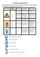
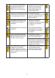
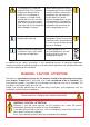
1. Danger classifications We differentiate between various different categories of safety instructions. The table shown below provides an overview of the assignment of symbols (pictograms) and signal words to the specific danger and the possible consequences.
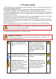
2. Product safety LUKAS products are developed and manufactured to ensure the best performance and quality when used as intended. The safety of the operator is the most important consideration in product design. Furthermore, the operating instructions are intended to help in using LUKAS products safely.
In the event of malfunctions, immediately deactivate the equipment and secure it. Repair the fault immediately. Do not carry out any changes (additions or conversions) to the equipment without obtaining the approval of LUKAS beforehand. Observe all safety and danger information on the device and in the operating instructions.
The equipment is filled with hydraulic fluid. This hydraulic fluid can be detrimental to health if it is swallowed or its vapour is inhaled. Direct contact with the skin must be avoided for the same reason. Also, when handling hydraulic fluid, note that it can negatively affect biological systems. When working with or storing the equipment, ensure that the function and the safety of the equipment are not impaired by the effects of severe external temperatures or that the equipment is damaged in any way.
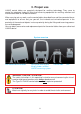
3. Proper use LUKAS control tables are especially designed for rerailing technology. They serve to control the deployed hydraulic lifting and traversing equipment for rerailing, erection and maintenance work on rail-bound vehicles.
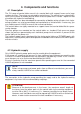
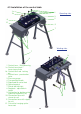
4. Components and functions 4.1 Description The CU range of control tables consist of a control desk with support frame and a large number of valves. The valves are actuated by control levers. The control levers automatically return to the neutral or middle position when released (dead man's handle - depressurised circulation with hydraulic load holding).
4.
4.
Controlling double-acting hydraulic equipment The double-acting hydraulic equipment is actuated by 4 or 8 (on the CU 4DW) control levers on the drive side. The CU 4DW control table corresponds to two CU 2DV control units mounted on a larger control table. Operating the CU 4DW control table is analogue to that of the CU 2DV.
Moving the control lever to the middle (preselection valve is actuated) on the operator side, in each case the left or right side is pressurised. After moving the middle lever to one side, the condition of the other side remains static. 5. Erection and start-up The control tables must be set up at a sufficiently safe distance from the loads to be lifted or moved. Both the load and the operating equipment must be easily observed from the control table. Make sure that the control table is standing securely.
5.1 Folding out the support frame The support frame ensures secure mounting of the control unit and allows to operator to work standing upright. The control unit is delivered in the folded transport position. Proceed as follows to erect the system (two people required): 1. Lift the control table with the handles at the side. Place your hands in the handles on the left and right, that are located opposite the locking knob, in each case, in order first to fold out the lower support frame. 2.
5.2 Connection of the working equipment On the double-acting hydraulically-actuated working equipment, there is, on the pressure supply side (with cylinders: the cylinder base side) a quick-disconnect nipple, and, on the return side (piston rod side) a quick-disconnect sleeve; and these are connected to the control table using a pair of extension hoses. On the hose ends we connect, in each case, a nipple on the sleeve on the end equipment and a sleeve on the nipple on the end equipment to prevent mix-ups.
NOTE: Coupling of the devices is only possible, when the hoses are depressurized. For dust protection, the supplied dust caps must be refitted. WARNING / CAUTION / ATTENTION! Some quick-disconnect couplings have special functions.Therefore, you must not unscrew them from the hoses or swap them over! 6.
Inspections to be carried out: Visual Inspection • Control table free from damage and deformation • General tightness (leaks), • Handle present and secure, • All screwed connections tight • Type plate, warning signs and other markings present and legible, • Couplings must be easy to couple, • Dust protection caps must be available, • All accessories used not damaged Functional test • Perfect ease of movement of the control levers • No unusual noises 7. Maintenance and service 7.
7.1.3 Replacing the hydraulic fluid After approx. 200 deployments, but after three years at the latest, replace the hydraulic fluid in the entire rerailing installation. Because of the small quantity of hydraulic fluid in the control table, separate fluid replacement on the control table is not required. It is adequate to flush the entire installation with the new hydraulic fluid during fluid replacement.
8. Troubleshooting Fault Connected working equipment moves slowly or jerkily when activated The connected working equipment does not move when actuated and no pressure indication on the control table pressure gauge. Check Cause Vent the hydraulic system Working unit defective. Consult the separate operating instructions for the working equipment. Are the hoses connected properly? Hose connection to hydraulic power pack not made, or made incorrectly. Connecting hose assemblies properly.
Hoses cannot be coupled Lines are under pressure because there is pressure in the system Remove the pressure or residual pressure (see Page 12) Coupling defective Coupling must be replaced immediately Leak from the couplings Is the coupling damaged? Coupling defective Coupling must be replaced immediately Cylinders automatically lower under load Check position of pressure relief valves Operating error Switch pressure relief valve to position I Contact an authorised LUKAS dealer or the LUKAS Cus
9. Technical data Because all values are subject to tolerances, there may be small differences between the data for your device and the data in the following tables! 9.1 Control unit CU 2DV Device type CU 2DV Item number 70-70-10 Dimensions lxwxh Dimensions lxwxh Operating pressure max. Value Units Remarks 1030 x 640 x 1112 mm set up 40.6 x 25.2 x 43.8 in. 1030 x 640 x 450 mm 40.6 x 25.2 x 17.7 in.
9.2 Control unit CU 4 DVV Device type Item number Dimensions Dimensions CU 4DVV Value Units Remarks 1310 x 640 x 1112 mm set up 51.6 x 25.2 x 43.8 in. 70-20-20 lxwxh lxwxh 1215 x 640 x 450 mm 47.8 x 25.2 x 17.7 in. 53 MPa Operating pressure max.
10.
11.
Please dispose of all packaging materials and removed items properly. LUKAS Hydraulik GmbH A unit of the IDEX Corporation Tel.: (+49) 0 91 31 / 698 - 0 Fax.: (+49) 0 91 31 / 698 - 394 e-mail: lukas.info@idexcorp.com www.lukas.com Made in GERMANY CU_2DV_4DVV_manual_1490000085_en.