
User manual


DEFINITY Enterprise Communications Server Release 6
Maintenance for R6vs/si
555-230-127
Issue 1
August 1997
Maintenance Commands and Trouble-Clearing Aids
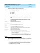
Page 8-54display communication-interface
8
Field descriptions
Link The physical link number.
Enabled A y (yes) indicates the link is enabled for normal operation.
A n (no; default) indicates that the message flow over the link is
suppressed. The link can only be enabled if the corresponding
data module has been administered.
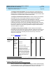
X.25 Extension The extension of the TN577 Packet Gateway port through which
the link is routed.
Destination
Number
The entry “external” indicates the link goes to equipment
connected locally to an external port on a Packet Gateway
circuit pack. Such ports must show a y in the Establish
Connection field.
Establish
Connection
This field indicates whether the local switch is responsible for
any part of call set-up with the far-end data module. If the
physical link is through a pair of data modules, each switch
terminating the link must set up a connection to its PDM/TDM. If
the physical link is over a DS-1 interface, it is possible for one
switch to set up the entire connection without any initiation by
the other end. The ISDN signaling links must be set to “y” at
both ends of the interface.
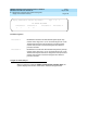
Connected Data
Module
The extension of a PDM/MPDM directly connected to a PGATE
port cable or to an adjunct in an administered connection
arrangement.
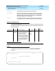
display communication-interface links SPE A
INTERFACE LINKS
X.25 Destination Establish Connected
Link Enabled Extension Number Connection Data Module Identification
1: y 5464 external y AUDIX ID1
2: n 5461 external y 5460 AUDIX-ADM-CONN1
3: y 5466 external y CMS-ADM-CONN-2
4: n
5: n
6: n
7: n
8: n
9: n
10: n
11: n
12: n
13: n
14: n
15: n
16: n