
User manual


LED Interpretation
Page 7-1General
7
DEFINITY Enterprise Communications Server Release 6
Maintenance for R6vs/si
555-230-127
Issue 1
August 1997
7
7
LED Interpretation
General
The lighting and unlighting of LEDs indicates to the system user the status of
various maintenance components in the system. LEDS are located on the
attendant console, on all circuit packs in the switch cabinets and, optionally, on
customer-designated voice terminals. The following LEDS are included in the
system:
■ Processor circuit pack and maintenance circuit pack LEDs
■ Duplication interface circuit pack LEDs
■ Attendant console LEDs
■ Carrier power unit LEDs
■ Power distribution unit LEDs
■ Control and port circuit pack status LEDs
Processor and Maintenance Circuit
Pack LEDs
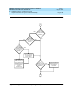
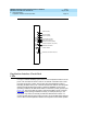
The front panels of the Processor circuit pack and the Maintenance circuit pack
are identical. Each has two groups of LEDs. One group indicates the status of the
pack, and the other group (which includes the Major, Minor, and Warning alarms
described previously) reflects maintenance conditions in the entire system (that
is, the PPN and EPN cabinets). See Figure 7-1
.
■ Red (alarm)—the system has detected a fault in this circuit pack.