Page 1 of 1 DNCP Series 400/400-CO (PA-8500) Hardware Installation Guide (FTX systems) Revision 0.
Technical Service Guide Copyright© 2000 Lucent Technologies. All Rights Reserved. This material is protected by the copyright laws of the United States and other countries. It may not be reproduced, distributed, or altered in any fashion by any entity (either internal or external to Lucent Technologies), except in accordance with applicable agreements, contracts or licensing, without the express written consent of Lucent Technologies, Inc.
Manual Conventions Manual Conventions For standardization purposes, the following conventions will be used throughout this manual ● Bolded Text is used for information which needs to be emphasized ● Italicized text is used for information which needs to be identified, such as component names or a specific system status The following conventions relate primarily to the software sections: ● Courier new bold text is used to indicate commands the user is to type.
Installation Guide 1. Preparing to Install the System ● Safety Considerations ● Required Tools ● System Description-- for DNCP Series 400 (PA-8500) Cabinet ● System Description-- for DNCP Series 400-CO (PA-8500) Cabinet ● Status Lights ● System Peripherals 2.
Chapter 1 Chapter 1 Preparing to Install the System This chapter contains important information to read before proceeding with the installation, such as a system description and vital safety considerations. This chapter is divided into the following sections. ● Safety Considerations ● Required Tools ● System Description 1.1 Safety Considerations Before installing the system, be sure to take the following important precautions.
Chapter 1 in standby mode , with one component online, while the other "stands by" to take over operation should its partner fail. The DNCP Series 400 (PA-8500) must be installed by a qualified service technician, but most of the components are customer-maintainable. Its data communications subsystem, based on a Peripheral Component Interconnect (PCI) bus, utilizes state-of-the-art PCI cards.
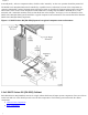
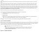
Chapter 1 ● System Ventilation 1.3a.1.1 DNCP Series 400 (PA-8500) Cabinet: Front Components For the components housed in the front of the cabinet, See Figure 1.2 which is also described in the following paragraphs. Figure 1.2. DNCP Series 400 (PA-8500) Cabinet: Front View The amber cabinet fault light, located at the top of the cabinet frame, above the doors, illuminates when one or more components within the cabinet have failed.
Chapter 1 Maximum duplexed storage capacity is 126 GB per disk shelf, 252 GB per DNCP Series 400 (PA-8500) cabinet (63GB per disk shelf, 126GB per system logical storage). Located at the bottom of the cabinet are duplexed logic suitcases. These suitcases house the system's central logic functions: the Hewlett-Packard CPUs, memory modules, and console controller, which is the system's central collection point for maintenance, diagnostic information and user interface.
Chapter 1 cables, and the alarm relay connector for remote alarm monitoring. Each power cable requires a separate AC electrical source. Below the power input region (AC power chassis) are two disk shelves which each contain three cooling fans, a SES (SCSI Enclosure Services) unit, a SE-SE (single-ended to single-ended) I/O repeater module and a terminator module. Below the disk shelves are two PCI card cages. Each card cage contains seven slots for PCI cards, for a total of 14 PCI cards per system.
Chapter 1 1.3b System Description for DNCP Series 400-CO (PA-8500) DNCP Series 400-CO (PA-8500) system combines the Hewlett-Packard PA-RISC PA-8500 microprocessor, system features rapid symmetric multiprocessing and continuously available hardware. Designed specifically for the CO environment, the system is fully CO-compliant, including support of Zone 4 seismic resilience standards. This system uses DC power. The DNCP Series 400-CO (PA-8500) system utilizes the FTX operating system.
Chapter 1 1.3b.1 System Description -- for DNCP Series 400-CO (PA-8500) Cabinet Each DNCP Series 400-CO (PA-8500) consists of a single cabinet that houses all major system components. Two sets of doors on the front and rear of the cabinet provide access to these components. The following sections describe the cabinet components. ● Cabinet: Front and Rear Components ● System Ventilation 1.3b.1.
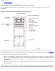
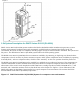
Chapter 1 The amber cabinet fault light , located at the top of the cabinet frame, above the doors, illuminates when one or more components within the cabinet have failed. (For a more detailed explanation of system status lights, refer to the Appendix. Four duplex power supplies are located just below the cabinet fault light: the top two power the ACUs, and the bottom two power the PCI card cage bays. To the right of the power supplies are two Alarm Control Units (ACUs).
Chapter 1 Figure 1.7. DNCP Series 400-CO (PA-8500) Cabinet: Rear View The top of the cabinet has a cable opening that provides access for routing system power cables and communications cables. The top of the cabinet frame has an amber cabinet fault light that illuminates when a component within the cabinet has failed.
Chapter 1 explanation of the RSN, refer to FTX System Administrator's Guide: General Services (R455X) The bottom of the cabinet also has a cable opening for routing power and communications cables. 1.3b.1.3 System Ventilation Ensure adequate air flow around the system during installation. The system requires two feet of clearance on the front and rear of the cabinet, and a minimum of 18 inches of unobstructed area above the top of the cabinet.
Chapter 1 component troubleshooting procedures. 1.5 System Peripherals The DNCP Series 400/400-CO (PA-8500) can include the peripherals described in the following sections. ● V105 Terminal ● C419/C619 Modem ● Tape and CD-ROM Drives V105 Terminal The V105 terminal, which is shipped with most DNCP Series 400/400-CO (PA-8500) systems, is an ASCII character-mode terminal that can be configured to operate as a system console to display system error and status information.
Chapter 1 To troubleshoot and replace a failed C419/C619, see FTX Operating System: DNCP Series 400/400-CO (PA-8500) Operation and Maintenance Guide (RXXX). For other information on the C419/C619 modem, see the vendor manual shipped with the modem. Tape and CD-ROM Drives DNCP Series 400/400-CO (PA-8500) systems support the T800-series tape and the D85X CD-ROM drives. For information about tape drive operation and maintenance, refer to DNCP Series 400/400-CO (PA-8500): Tape Drive Operation Guide (R716).
Chapter 2 Chapter 2 Installing the Core System Components After unpacking the system, follow the instructions in this chapter to install the core system components. The core system components consist of the cabinet, V105 terminal, C419/C619 modem, and PCI cards. This chapter contains the following sections.
Chapter 2 4. Using a flat-blade screwdriver, remove the cable opening cover from the top of the cabinet (See Figure 2.2). Figure 2.2.
Chapter 2 5. Using the torque wrench, attach the ground cable that is shipped with the system to the back of the system cabinet (See Figure 2.3) , being careful not to apply more than 33 inch pounds of torque. The ground cable may be attached to the double ground lugs found on either the left or right side of the cabinet. Figure 2.3.
Chapter 2 6. Unpack the two system power cables from one of the cartons shipped with the system. The part number for each power cable appears on the cable and on the plastic bag in which the cable is shipped. Before connecting a power cable, always shut off both MAIN system power switches/AC input breakers on the same side of the cabinet. 7. Connect each power cable to the cabinet and into a separate AC power source.
Chapter 2 9. Since it is recommended that you limit the times the system is powered up and down, proceed to the system console instructions (See Section 2.2 Installing the System Console later in this chapter) before completing Step 10. 10. Turn on the cabinet MAIN power switches. The cabinet power supply lights are illuminated, indicating that the system is receiving power.
Chapter 2 (See Section 2.1b.2 Installing the Power Cables (Bottom Entry) ). Power cables are terminated with a two-hole universal lug. Depending on your site requirements, this termination may have to be customized. 1. Open the cabinet doors. 2. Verify that the four cabinet ground wires (two front, two rear) are connected from the cabinet frame to the doors. 3. Make sure that the two MAIN power switches on the front of the cabinet are in the off (0) position. (See Figure 2.5 ). Figure 2.5.
Chapter 2 side of the cabinet. Figure 2.6. Attaching the Ground Cable (Top of Cabinet) Figure 2.7.
Chapter 2 2.1b.1 Installing the Power Cables (Top Entry) Perform the following steps to route the power cables from the top of the system. 1. Using a flat-blade screwdriver, remove the cable opening cover from the top of the cabinet (See Figure 2.8). Figure 2.8. Removing the Cable Opening Cover 2. Unpack the two system power cables (AW-000955 and AW-000968) from one of the cartons shipped with the system.
Chapter 2 Be sure to connect each power cable to a separate DC power source . If they are plugged into the same source, a failure at the source will result in a system crash. 4. Using a digital voltmeter (DVM), measure the DC input voltage by connecting the leads to the input voltage test points below the DC input connector. Connect the black lead to the 48V (black) test point; connect the red lead to the -48V (red) test point. Verify that the voltage is within the range of -40.5 VDC to -60.0 VDC.
Chapter 2 ● ● ● is receiving power. If the lights do not illuminate, check the following: Incoming power sources Power cable connections to the power sources and cabinet The polarity of the power cables. See Figure 2.10 for power-cable polarity information; for additional electrical wiring information, see Appendix A of the DNCP Series 400/400-CO (PA-8500): Site Planning Guide (R454).) Figure 2.10.
Chapter 2 3. Using a digital voltmeter (DVM), measure the DC input voltage by connecting the leads to the input voltage test points below the DC input connector. Connect the black lead to the 48V (black) test point; connect the red lead to the -48V (red) test point. Verify that the voltage is within the range of -40.5 VDC to -60.0 VDC. If the input voltage is not within the specified range, do not proceed to the next step. Verify the DC power input source. 4.
Chapter 2 2.2 Installing the System Console If you are using a V105 terminal as the system console, connect it to the cabinet as described in the following procedure. If you are using another terminal as the system console, be sure it is configured with the following parameters. ● VT300/7 terminal emulation ● ● ● 9600 EIA and auxiliary (Aux) baud rate odd parity one stop bit To install a V105, follow these steps. 1.
Chapter 2 3. Connect the keyboard to the terminal (See Figure 2.13) . Keyboard AA-V10501 is an ANSI keyboard and AA-V10502 is a PC keyboard. Figure 2.13.
Chapter 2 4. Connect the female end of the V105 power cord to the V105 power connector and the male end to an AC wall outlet (See Figure 2.14). Figure 2.14. Connecting the V105 Power Cord 5. Power up the V105 by pressing the power switch on the front of the terminal to the ON position (See Figure 2.15) . When the V105 passes its self-test, its screen displays PASS . If this does not occur, turn off the V105 power switch, check its power cord connection, and then power it up again.
Chapter 2 6. If needed, adjust the screen contrast and brightness using the dials (See Figure 2.16). Figure 2.16. V105 Operating Dials 7. To access the V105's configuration screens, press the key (ANSI keyboard) or hold down the key while pressing the key (PC keyboard). 8. When the V105 displays the setup screen keys, press the < F1 Quick> key. The V105 now displays the Quick Setup screen, (See Figure 2.17 ). Figure 2.17.
Chapter 2 9. Set the values (See Figure 2.17) . To change the values, press the appropriate "arrow key" (up, down, left right) to select a field. Then, press the space bar to select the correct value. 10. Save these changes and exit the Quick Setup screen by pressing the key. 11. The V105 displays the prompt, Save all? (Y/N) . Press the key to save the values selected or the key to exit without saving them.
Chapter 2 2. Some CX19 modems have a dial-up/leased-line switch on the side. If the modem being used does, verify that the switch is in the up position (See Figure 2.19) . If the modem does not have this switch, continue with step 3. Figure 2.19. Modem Dial-Up/Leased-Line Switch 3. Locate the 16 DIP switches and verify that they are set CORRECTLY (See Figure 2.20). If necessary, use the end of a paper clip, or similar pointed instrument, to change the switch settings. Figure 2.20.
Chapter 2 4. Connect one end of the telephone cable to the modem LINE connector and the other end to the telephone wall jack, (See Figure 2.21) . Figure 2.21. Connecting the Modem Telephone Cable 5. Connect the RS-232 cable (AW-B10102-25) to the modem EIA RS-232-C connector (See Figure 2.22). Tighten the connector screws with a flat-blade screwdriver. Figure 2.22.
Chapter 2 6. Attach the adapter (part number JD-025PLG-07) to the RSN port (J317) on the cabinet, then connect the RS-232 cable to the adapter (See Figure 2.23 ). Figure 2.23.
Chapter 2 7. Connect the power cord to the modem POWER connector and to an AC wall outlet (See Figure 2.24) . Figure 2.24. Connecting the Modem Power Cord 8. Turn the modem power switch to ON (See Figure 2.25) . Figure 2.25. Modem Power Switch 9. After it is powered on, the modem performs a self-test. During the modem self-test, the five speed indicators on the front of the modem flash in sequence for approximately four seconds.
Chapter 2 outlet is live. If the AC outlet is live and the modem still does not work, the modem may be faulty. 10. Verify the operation of the telephone line by plugging a telephone into the modem's PHONE port. Pick up the telephone receiver and dial a known working number. If unable to get a connection, this phone line has not been activated. Contact the telecommunications contractor or phone company to remedy the problem. 2.
Chapter 3 Chapter 3 Installing Tape Drives After the core system components are installed, tape drives can be installed. For each U501 SCSI PCI card in the system, the following can be configured: ● one stand-alone T800-Series tape or D85X CD-ROM drive (or) ● two daisy-chained T800-Series tape or D85X CD-ROM drives This chapter explains how to install tape drives.
Chapter 3 2 0 7 1 2 0 7 1 7 N N DPT SCSI Controller 3 0 7 1 3 0 7 1 7 N N DPT SCSI Controller 2 0 7 2 2 0 7 2 7 N N DPT SCSI Controller 3 0 7 2 3 0 7 2 7 N N DPT SCSI Controller 2 0 7 0 2 0 7 0 7 Y Y DPT SCSI Controller 3 0 7 0 3 0 7 0 7 Y Y DPT SCSI Controller For more information about the vsbconf command, see the FTX System Administrator’s Guide: General Services (R455X). 2. Issue the /sbin/hwmaint stop command to suspend operation on the target bus.
Chapter 3 Part Number Description AA-T80500 AA-T80600 T800-Series Tape Drive AW-B12800- XX Power Cord AW-B21000-12 SCSI Cable JC-005TRM SCSI Terminator AX-T60007 Data Cartridge (T805 and T806) AX-T60006 Autoloader magazine (T806) AX-T60002 Cleaning Cartridge (T805 and T806) Parts included with the Stand-Alone T800-Series Tape Drive. (See Figure 3.1) Figure 3.1. T800-Series Parts: Stand-Alone Tape Drive 2. Place the tape drive on a table or rack near the rear of the system cabinet.
Chapter 3 3. Verify that the SCSI identification display on the tape drive is set to 0, See Figure 3.2. If it is not, use a paper clip (or similar nonmarking, pointed instrument) to press the buttons to increase or decrease the number. Press the upper button to decrease the number and the lower button to increase it. Do not press the upper button after the number 0 is displayed, or the lower button after 7 is displayed. Attempting to move beyond these parameters will break the buttons. Figure 3.2.
Chapter 3 5. Turn off the power switch on the tape drive, See Figure 3.4. Figure 3.4. Powering Down the T800-Series 6. Connect the SCSI cable (part number AW-B21000-12) to the rear of the tape drive and to the U501 SCSI card in slot 7 of either PCI card cage, See Figure 3.5. Figure 3.5.
Chapter 3 7. Plug the power cord into the rear of the tape drive and into an AC wall outlet, See Figure 3.6. Figure 3.6.
Chapter 3 8. Turn on the T800-Series power switch, See Figure 3.7. The green power light is illuminated as long as the tape drive is receiving power. If it is not illuminated, check to be sure the cables are securely connected. Figure 3.7. Powering Up the T800-Series 9. When the system is booted, the tape drive will come online, as described in Chapter 4, "Booting the System." 3.
Chapter 3 Items Included with Daisy-Chained T800-Series Tape Drives Part Number Description AA-T80500 AA-T80600 T800-Series Tape Drive AW-B12800- XX Power Cord AW-B21000-12 SCSI Cable AW-B20000 SCSI Daisy-Chain Cable JC-005TRM SCSI Terminator AX-T60007 Data Cartridge (T805 and T806) AX-T60006 Autoloader magazine (T806) AX-T60002 Cleaning Cartridge (T805 and T806) Parts included with the Daisy-Chained T800-Series Tape Drive. (See Figure 3.8) Figure 3.8.
Chapter 3 2. Place the tape drives on a table or rack near the rear of the system cabinet. 3. Verify that the SCSI identification display on the tape drive that will be connected to the SCSI PCI card is set to 0. Verify that the SCSI identification display on the other tape drive in the daisy-chain is set to 1, See Figure 3.9.
Chapter 3 To change the SCSI identification on a T800-series tape drive, first power down the tape drive. The SCSI identification is read by the system when the tape drive is powered up. If you change the SCSI identification display after power-up, the new identification will not be registered by the tape drive. Any attempts to access the tape drive will result in an application error. 4.
Chapter 3 If the tape drive is the first drive in the daisy chain and a terminator is connected to either tape-drive port, remove the terminator. 5. Turn off (0) the power switch on each tape drive, See Figure 3.11 . Figure 3.11. Powering Down the T800-Series( 2nd) 6. Connect the SCSI cables, (part number AW-B21000-12) to the rear of the tape drive and to the U501 SCSI card in slot 7 of the PCI card cages. See Figure 3.12. Figure 3.12.
Chapter 3 7. Plug the power cords into the rear of each tape drive and into AC wall outlets, See Figure 3.13. Figure 3.13.
Chapter 3 8. Turn on the power switch on the rear of each tape drive, See Figure 3.14. The green power light on each tape drive is illuminated and remains lit as long as the tape drive is receiving power. If the light does not illuminate, check to be sure that the power cables are securely connected. Figure 3.14. Powering Up the T800-Series (2nd) To change the SCSI identification on a T800-Series tape drive, first power down the tape drive.
Chapter 3 To complete the installation of a tape drive on a running DNCP Series 400/400-CO (PA-8500) system, perform the following steps. 1. Issue the /sbin/hwmaint start command to activate the SCSI bus. /sbin/hwmaint start vsb n In the preceding example, n is the virtual SCSI bus location (either 2 or 3) that you suspended before installing the tape drive. 2. Issue the /sbin/hwmaint ls command to verify that the state of the VSB is now onln.
Chapter 4 Chapter 4 Booting the System This chapter describes how to boot the system. Boot the system by performing the following steps. 1. Verify that cabinet components are seated properly by checking that their thumbscrews are fully tightened. 2. Verify that the flash cards are fully inserted in the bridge cards in slot 0 of each PCI card cage. 3. Power up the system console. 4.
Chapter 4 Wait approximately 10 seconds for the system boot to begin. When the system begins to boot, the CABINET FAULT and component lights flash on and off. As the booting progresses, the logic suitcase lights are illuminated in the sequence listed (See Logic Suitcase Power-Up Light Sequence) . Logic Suitcase Power-Up Light Sequence Power-UpStage Color State Red Off 1 Yellow On Green Red 2 The logic suitcase is performing its self-test.
Chapter 4 Services (R455X) for instructions on how to perform a manual boot. 5. As the booting progresses, the system console displays a series of messages similar to the following sample output. Continuum Firmware, Version xx.y (G2xx) (copyright) 1995-1998 by Ascend Communications, Inc.
Chapter 4 Welcome to UNIX System V/PA-RISC Release x.x System name: system_name Console login: root New password: Re-enter new password: The system displays additional messages followed by the # command line prompt. When you see this prompt, the system has successfully booted. 9. Close the cabinet doors. Next, configure the RSN as described in Chapter 5, Configuring the RSN and C419/C619 Modem .
Chapter 5 Chapter 5 Configuring the RSN and C419/C619 Modem This chapter describes how to configure the Remote Services Network (RSN). It contains the following sections. Preparing to Configure the RSN Configuring the RSN Configuring the C419/C619 Modem Completing and Verifying Configuration of the RSN For more information on how to configure the RSN, see HP-UX Operating System: Fault Tolerant System Administration (R1004H-04-ST). 5.
Chapter 5 /usr/stratus/rsn/bin/rsnon This script displays the following message and prompt. Press the key to continue. 1. Setting rsn_monitor, rsn_getty, rsndbs to respawn in /etc/inittab. 2. Enabling the rsntrans entry in /var/spool/cron/crontabs/rsn. 3. If any errors are encountered, no changes are committed. Press return to continue or q to quit... The script displays the RSN inittab settings and asks you if they are correct. The settings should be correct.
Chapter 5 ************************************************** ************************************************** # 2. Enter the /usr/stratus/rsn/bin/rsnadmin command to display the RSNADMIN MAIN MENU .
Chapter 5 the set menu item in order to specify the bridge_system_path entry. For example: BRIDGE SYSTEM PATH MENU 1) get get current bridge_system_path 2) set set current bridge_system_path Options: [#, command, ?command (help for command), 0 (parent menu), / (goto main menu), q (quit rsnadmin)] Command: 2 The bridge_system_path entry identifies the NFS mount path of the root directory on the bridge system. A bridge system such as the PA-8500 Continuum Series 400 system is attached to an RSN modem.
Chapter 5 ORDER NO.: US 113370 SHIP-TO: 01923 BILL-TO: 01932 SID TECH: J. Bond Company X Company X 55 Main Blvd. 55 Main Blvd. SHIPPER: XXX Inc. Boston, MA 02116 Boston, MA 02116 USA USA CPU SER:60029 RA KIT:N INSP BY:M.Jones SITE SR: N/ A___Y___N__ ATTN:PAM SMITH ATTN: PHONE:X2502 PHONE: SITE-ID: comp_ux ORDER STATUS: APPROVED If necessary, a different site ID of up to 16 characters can be specified. For example: Enter new site_id: cac_ux If the site ID is changed, immediately inform the CAC.
Chapter 5 SITE_INFO MENU 1) 2) 3) 4) 5) 6) 7) list list all site_info hub_phone_1 hub_phone_1 menu hub_phone_2 hub_phone_2 menu rsn_password set rsn_password nighttime nighttime menu cleanup cleanup menu scs_in_use scs_in_use Options: [#, command, ?command (help for command), 0 (parent menu), / (goto main menu), q (quit rsnadmin)] Command: 2 This displays the menu called HUB_PHONE_1 MENU . 11.
Chapter 5 To recover from the error, start RSN by executing the /usr/stratus/rsn/bin/rsnon command at the operating system # prompt. Then execute the /usr/stratus/rsn/bin/rsnadmin command to display the RSNADMIN MAIN MENU . Enter 4 to display the SITE_INFO MENU . You can now set the hub phone number by entering 2 at the Command: prompt. If you do not have a direct outside telephone, have one installed as soon as possible.
Chapter 5 Command: 5 This displays the menu called NOTIFY_LIST MENU . 14. At the Command: prompt at the end of NOTIFY_LIST MENU , enter the value 4 to select the add_both menu item to add your login name or the system administrator's login name to the list.
Chapter 5 3. Execute the following script to configure the C419/C619 modem. For more information on the rsninitmodem script, see the rsninitmodem man page. /usr/stratus/rsn/bin/rsninitmodem The script displays the following messages as it configures the modem. Wait ... .............................................. Verifying .................. Saving .... /usr/stratus/bin/rsninitmodem: Done 5.
Chapter 5 /etc/inittab. 2. Enabling the rsntrans entry in /var/spool/cron/crontabs/rsn. 3. If any errors are encountered, no changes are committed. Press return to continue or q to quit... The script displays the RSN inittab settings and asks you if they are correct. The settings should be correct. Press y followed by the key to continue.
Chapter 5 /usr/stratus/rsn/bin/rsntry The script calls the hub telephone number you specified with rsnadmin and attempts to verify the connection. If the script concludes with a success message, the RSN is installed and configured correctly. The system then displays the root prompt. You can now prepare and send the installation report. /usr/stratus/rsn/bin/rsntrans -r1 -sHUB -z -f -x0 waiting for connect message.....
Chapter 6 Chapter 6 Sending the Installation Report After the RSN is configured , an installation report must be prepared and sent to the CAC. The installation report provides valuable information that enables the CAC to support the site and track product quality issues. This chapter contains the following sections. ● See Preparing an Installation Report ● See Sending an Installation Report to the CAC ● See Sample Installation Report 6.
Chapter 6 Enter Selection (1 2): 1 4. A prompt asks for verification of the system site ID. The default site ID is the same as the site ID on the S.O. (Sales Order) pick list which arrived with the shipping carton (shown in bold in the example below). Report Name: COP-3136 1 Report Date: 05/15/99 S.O. PICKLIST Page: ============= BILL OF MATERIAL EFFECTIVITY DATE: 05/15/99 ORDER NO.: SHIP-TO: Bond US 113370 01923 BILL-TO: 01932 SID TECH: J. Company X 55 Main Blvd. Company X 55 Main Blvd.
Chapter 6 Zip: 01752 The script then prompts you to enter the sales order number. Sales Order Number: 113370 Find the order number (ORDER NO) on the picklist, as shown in bold below. Report Name: COP-3136 Report Date: 05/15/99 S.O. PICKLIST ============= Page: 1 BILL OF MATERIAL EFFECTIVITY DATE: 05/15/99 ORDER NO.: SHIP-TO: US 113370 01923 BILL-TO:01932 SID TECH: J. Bond Company X Company X 55 Main Blvd. 55 Main Blvd. SHIPPER: XXX Inc.
Chapter 6 8. The script also prompts you to enter the following information. System Administrator: Beth Smith System Admin Phone No.: 1-508-999-9898 Installer: Beth Smith Total Install Hours: 5 Is the RSN installed (yes/no)? y User Name for CAC Access: beths 9. The script then prompts you to enter the password for the CAC user specified when the RSN was configured. For more information, See Configuring the RSN and C419/C619 Modem. Password for CAC User: beths 10.
Chapter 6 11. The script then asks seven yes/no questions about your experience with the installation process. After entering y (yes) or n (no) in response to a question, press the key to move to the next question. Although the use of the name Stratus is retained throughout the scripts, the references below pertain to Lucent. ** Answer the following 7 yes/no questions to complete the data entry portion of the install report.
Chapter 6 14. After a method is chosen, refer to the next section, "Sending an Installation Report to the CAC," for report-sending instructions. 6.2 Sending an Installation Report to the CAC The following sections, Sending the Installation Report Via the RSN , Sending the Installation Report Via the Internet , and Saving the Installation Report to a Temporary File, describe methods for sending the installation report to the CAC.
Chapter 6 6.2.3 Saving the Installation Report to a Temporary File In situations where the installation report must be sent at a later date via the RSN or Internet, or if the contents of the report to CAC personnel are read during a voice telephone call, specify the value 3 on the install_report script to save the installation report to a temporary file. The script displays the following information. A version of the installation report is always automatically saved in the /tmp directory.
Chapter 6 Were you able to successfully install your system by utilizing the Stratus supplied product Installation documentation? ==> YES Were there any hardware installation problems? ==> NO Were there any software installation problems? ==> NO Additional Comments (optional): We have a fairly simple configuration and the installation went quite smoothly.
Chapter 6 M704 k13800 pci 0 e525 u51000 0 u50100 OST1 k13800 pci 0 e525 u50100 OST1 - Physical MEM/2*128M 1 1 Physical CPU 1 2 PCI Bridge Board 2 PCI Bus 0 2 0 PCI Physical Bus 2 0 pci 0 PCI Physical Bus 2 0 pci 1 PPEC Bridge Cntrllr 2 0 0 20MB Centen Flash C 2 0 0 0 10/100Mbps Ethernet 2 0 2 Ethernet( 10 Mbps) 2 0 2 0 SCSI Ctlr (W/SE) 2 0 7 SCSI port 0 2 0 7 0 Logical SCSI Cab 0 2 0 7 0 cab SCSI Port 1 2 0 7 1 Logical SCSI Cab 1 2 0 7 1 cab SCSI Port 2 2 0 7 2 Logical SCSI Cab 2 2 0 7 2 cab PCI Bridge Bo
Chapter 6 d84200 0016 d84200 0016 d84200 0016 d84200 0016 t80500 9503 cab e25500 e25500 d820 d820 e611 e611 e611 e611 p272 p272 p271 - Virtual SCSI Bus 0 vsb 0 Virtual SCSI Tray vsb 0 0 18GB SCSI Disk Drive vsb 0 0 0 Virtual SCSI Tray vsb 0 1 18GB SCSI Disk Drive vsb 0 1 0 Virtual SCSI Cab 0 vsb 0 cab Virtual SCSI Bus 1 vsb 1 Virtual SCSI Tray vsb 1 0 18GB SCSI Disk Drive vsb 1 0 0 Virtual SCSI Tray vsb 1 1 18GB SCSI Disk Drive vsb 1 1 0 Virtual SCSI Cab 1 vsb 1 cab Virtual SCSI Bus 2 vsb 2 Virtual SCSI T
Chapter 6 p271 p274 p274 - ] Disk Power cab 0 dps 1 Main breaker cab 0 mps 0 Main breaker cab 0 mps 1 - - --- - 4 - - --- - - - - --- - -
Appendix - Fault Isolation Appendix A. Fault Isolation This section contains information used to troubleshoot faults in the system. It contains the following subsections: Component Status LEDs System Error Log A.1 Component Status LEDs A.1.1 General LED information LEDs can be in a three color arrangement, a two color arrangement or a single light. General explanations or these categories follow A.1.1.
Appendix - Fault Isolation If the amber cabinet fault LED (at the very top of the cabinet-- front and rear) is illuminated, a CRU within the cabinet has produced an error condition. [Both cabinet fault lights (one front and one rear) are lit when one or more components within the cabinet has failed. ] If the amber PCI fault status LED is lit, there is an error within the PCI card cage. The PCI Fault status LED is located on the front of the cabinet, at the bottom of the disk shelves.
Appendix - Fault Isolation A.2.1 Power Supply LEDs A.2.1.
Appendix - Fault Isolation Green On DC output power good. Green On AC input power good. Red Off Green Off Green On AC input power good. Red DC output power fault. On Green Off Green Off Red Unit faulty and needs service. On Green Off Green Off Red Power is off. Off A.2.2 Disk Shelf LEDs A.2.2.1 Disk Power Supply LEDs A.2.2.3 SE/LVD Terminator Module This unit is located above the three fan modules on the right of each of the two disk shelves (rear).
Appendix - Fault Isolation The red LEDs in the Fan units should not be illuminated. If a red LED is on in one of the fan units, that unit should be replaced as soon as possible (the system is capable of running with only two fans but it is recommended that all three fans be operational at all times). A.2.3 Suitcase LEDs In this section, refer to Figure A-3 for an illustration of the suitcase LEDs. Figure A-3. Suitcase with LEDs identified A.2.3.1 Suitcase Power-On LED Sequence A.2.
Appendix - Fault Isolation A.3 System Log and Status Messages System logs contain information concerning major system events and the time they occurred which can help detect and evaluate system problems. Each time a significant event occurs, the syslog message logging facility enters an error message into the systemlog at /var/adm/syslog/syslog.log. Depending upon the severity of the error and the phase of system operation, the same message might also be displayed on the console.
Appendix - Fault Isolation A.4 Component Status The ftsmaint ls command lists the components in the system and identifies any components that have been removed from service. The list serves as a simple troubleshooting tool to verify that all the components are present and shows their status (in/out of service). Refer to PA-8500 Continuum Series 400 Technical Service Guide (HP-UX systems), Section 2.6.3 to view a sample ftsmaint ls output screen. A.4.
Appendix - Fault Isolation Duplexing device is in the process of duplexing. This transient status is displayed after the ftsmaint sync or ftsmaint enable command has been used on the CPU-Memory board. Offline The device is not functional or not being used. Burning PROM Offline Standby The ftsmaint burnprom command is in progress on the device. The suitcase stays in offline standby when burning PROM. The status of a hardware component can change.
Appendix - Fault Isolation CABLE PCI Power Cable Missing This PCI backpanel cable is not attached. CABPCU Cabinet Power Control Unit Fault A power control unit faulted. CABPSU Cabinet Power Supply Unit Fault A power supply unit faulted. CABPWR Broken Cabinet Power Controller A cabinet power controller failed. CABTMP Cabinet Battery Temperature Fault A cabinet battery temperature above the safety threshold was detected.
Appendix - Fault Isolation deleted. MTBF Below MTBF Threshold The CRU/FRU’s rate of transient and hard failures became too great. NOPWR No Power The CRU/FRU lost power. OVERRD Cabinet Fan Speed Override Active The fan override (setting fans to full power from the normal 70%) was activated. PC Hi Power Controller Over Voltage An over-voltage condition was detected by the power controller. PCIOPN PCI Card Bay Door Open The PCI card-bay door is open.
Appendix - Fault Isolation Troubleshooting Flow When troubleshooting system faults, use the following process: Check the console terminal for fault information. Locate the failed component(s) using the LEDs. Verify the component is bad by using software commands/error logs. Remove and replace the failed component. Check to make sure the problem is resolved.