
- Lucent Integrated Network Access Module Installation and Configuration Guide


B-1
Cable Specifications B
This appendix provides cable and pinout specifications.
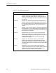
Cables Specified
• Console Cable. This null modem cable is used to connect a terminal or PC to the
console port of the INA module.
• T1/PRI Cable. This cable is used to connect a T1/PRI line to the INA module.
• Ethernet Interface Cable. This cable is used to connect the Ethernet connector on
the INA module to an Ethernet hub.
• Crossover Cable. This cable is used to make a simulated network connection
between the INA module’s Ethernet port and a free-standing computer workstation.
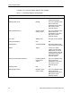
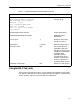
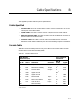
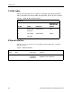
Console Cable
Table B-1 shows the cable pinouts for a RJ-45-to-DB-25 null modem cable. The INA
module does not use Data Set Ready (DSR).
Table B-1 Console Cable Pinout
INA Module
Serial Port (C0)
PC or terminal
Serial Port
RJ-45 Name Definition Direction
DB-25
(DTE) Signal
1 RTS Request to Send Output 5 CTS
2 DTR Data Terminal Ready Output 8
1
1. Pins 8 and 6 in the DB-25 connectors are connected internally.
DCD
3 TXD Transmit Data Output 3 RXD
4 GND Signal Ground NC
2
2. Not connected.
5 GND Signal Ground 7 GND
6RXDReceive Data Input2 TXD
7 DCD Data Carrier Detect Input 20 DTR
8 CTS Clear to Send Input 4 RTS
NC
2
Data Set Ready 6
1
DSR