MERLIN MAGIX™ Integrated Network Access (INA) Module Installation and Configuration Guide Lucent Technologies October 1999 7820-1000-001
Notice Every effort has been made to ensure that the information in this guide is complete and accurate at the time of printing. Information, however, is subject to change. Your Responsibility for Your System’s Security LUCENT DOES NOT WARRANT UNINTERRUPTED OR ERROR-FREE OPERATION OF THE PRODUCTS, INCLUDING MERLIN® INA.
Copyright and Trademarks © 1999 Lucent Technologies. All rights reserved. MLX-10, MLX-20L, MLX-28D, MLS-6, MLS-12, MLS-12D, MLS-18D, MLS-34D, PortMaster, ComOS, and MERLIN are registered trademarks and PMVision and MERLIN MAGIX are trademarks of Lucent Technologies. All other marks are the product of their respective owners.
Contents Safety Instructions Important Safety Instructions —SAVE THESE INSTRUCTIONS . . . . . . . . . . . . . . . . . ix About This Guide Audience . . . . . . . . . . . . . . . . . . . . . . . . . . . . . . . . . . . . . . . . . . . . . . . . . . . . . . . . . . . xi Related Documentation . . . . . . . . . . . . . . . . . . . . . . . . . . . . . . . . . . . . . . . . . . . . . . . xi MERLIN MAGIX Documentation . . . . . . . . . . . . . . . . . . . . . . . . . . . . . . . . . . . . .
Contents Connect a Serial Passthrough Cable . . . . . . . . . . . . . . . . . . . . . . . . . . . . . . . . . . . 3-1 Set DIP Switches . . . . . . . . . . . . . . . . . . . . . . . . . . . . . . . . . . . . . . . . . . . . . . . . . . 3-2 Connect a Console (Optional) . . . . . . . . . . . . . . . . . . . . . . . . . . . . . . . . . . . . . . . 3-3 Connect a T1/PRI Cable . . . . . . . . . . . . . . . . . . . . . . . . . . . . . . . . . . . . . . . . . . . . 3-3 Connect an Ethernet Cable . . . . . .
Contents Set the Destination IP Address . . . . . . . . . . . . . . . . . . . . . . . . . . . . . . . . . . . . . . . 5-7 Set the Netmask . . . . . . . . . . . . . . . . . . . . . . . . . . . . . . . . . . . . . . . . . . . . . . . . . . 5-7 Set the Transport Protocol . . . . . . . . . . . . . . . . . . . . . . . . . . . . . . . . . . . . . . . . . . 5-7 Apply Filters to the WAN Port (Optional) . . . . . . . . . . . . . . . . . . . . . . . . . . . . . . 5-7 6. Using PMVision Install PMVision . . .
Contents Current Events . . . . . . . . . . . . . . . . . . . . . . . . . . . . . . . . . . . . . . . . . . . . . . . . . . . C-5 Selected Interval Events . . . . . . . . . . . . . . . . . . . . . . . . . . . . . . . . . . . . . . . . . . . . C-5 Clearing Error Events . . . . . . . . . . . . . . . . . . . . . . . . . . . . . . . . . . . . . . . . . . . . . . C-5 Demand Tests . . . . . . . . . . . . . . . . . . . . . . . . . . . . . . . . . . . . . . . . . . . . . . . . . . . .
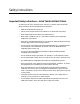
Safety Instructions Important Safety Instructions —SAVE THESE INSTRUCTIONS To reduce the risk of fire, electrical shock, and injury to persons, follow these basic safety precautions when installing telephone equipment: • Read and understand all instructions. • Follow all warnings and instructions marked on or packed with the product. • Never install telephone wiring during a lightning storm.
Important Safety Instructions —SAVE THESE INSTRUCTIONS x INA Module Installation and Configuration Guide
About This Guide The MERLIN MAGIX Integrated Network Access (INA) Installation and Configuration Guide provides installation and configuration instructions for the MERLIN MAGIX Integrated System (IS) Integrated Network Access (INA) module. The routing functions of the module are based on Lucent Technology’s PortMaster® series of products. The operating software for the module is the PortMaster ComOS® operating system. The operating software for the router is the PortMaster ComOS release 4.1.
Related Documentation Document No. Title 555-610-150 MERLIN LEGEND® Communications System, Release 6.1, Network Reference 555-710-800 Customer Reference CD-ROM: Consists of the System Manager’s Quick Reference, the Feature Reference, System Programming, and the Network Reference xii 555-710-123 (U.S. English) 4400/4400D Telephone User’s Guide 555-710-123FRC (Canadian French) 4400/4400D Telephone User’s Guide 555-710-127 (U.S.
Additional References Document No. Title 555-710-142 Installation, SPM, Maintenance and Troubleshooting Supplement 555-710-116 Pocket Reference 555-025-600 BCS Products Security Handbook PortMaster Documentation The following manuals are available from Lucent. Paper copies of these manuals can be ordered directly from Lucent. The manuals are also provided as PDF and PostScript files on the INA Module Software CD shipped with your module.
Document Conventions Document Conventions The following conventions are used in this guide: Convention Use Examples Bold font Indicates a user entry—a command, menu option, button, or key—or the name of a file, directory, or utility, except in code samples. • Enter version to display the version number. Identifies a command-line placeholder. Replace with a real name or value. • set Ether0 address Ipaddress Enclose optional keywords and values in command syntax.
Limited Warranty Limited Warranty Lucent Technologies provides a limited warranty on the INA module. Refer to “Limited Warranty and Limitation of Liability” in Appendix A, “Customer Support Information,” of System Programming manual (555-710-111). Technical Support In the USA Only. Lucent Technologies provides a toll-free customer Helpline (1-800-628-2888) 24 hours a day.
Subscribing to PortMaster Mailing Lists • portmaster-radius—a discussion of general and specific RADIUS issues, including configuration and troubleshooting suggestions. To subscribe, send email to majordomo@livingston.com with subscribe portmaster-radius in the body of the message. The mailing list is also available in a daily digest format. To receive the digest, send email to majordomo@livingston.com with subscribe portmaster-radius-digest in the body of the message.
INA Module 1 This chapter introduces the MERLIN Integrated Network Access (INA) module and provides an overview of its installation and configuration.
INA Front Panel 1. Arrange with your telecommunications service provider (telco) for a T1/PRI line. 2. Have the telco provision the line so that some channels are assigned to switched voice calls and the rest are assigned to one or more point-to-point data connections. 3. Use the system administration console to assign the voice channels to the MERLIN MAGIX switch and the data channels to the INA module router.
INA Front Panel Figure 1-1 INA Module Front Panel DS-1 status LEDs C1 serial port DIP switches system LED console port (C0) network activity LED Ethernet port (Ether 0) Ethernet link LED Reboot button T1/PRI port DS-1 test jacks 1210-001 DIP Switches. DIP switch 1 controls the configuration of serial port C0. DIP switch 2 controls ComOS boot behavior. See “Set DIP Switches” on page 3-2. System LED. This LED indicates the status of the routing hardware and the ComOS.
Installation and Configuration Steps Ethernet Port. This RJ-45 connector provides a 10BaseT Ethernet connection. See “Connect an Ethernet Cable” on page 3-4. Ethernet Link LED. This green LED indicates link integrity to a 10BaseT hub. See “Ethernet LEDs” on page 3-6. Reboot Button. This button resets the router hardware and reboots ComOS. It has no effect on MERLIN MAGIX voice operation. You will need a thin object such as a straightened paper click to activate this recessed switch. T1/PRI Connection.
Getting Ready for Configuration 2 To properly configure your INA module, you must gather all the technical information needed. You must also assign T1/PRI channels using the MERLIN MAGIX administration console before using the INA module.
Network Settings for PRI configurations and channel signaling types for T1 configurations. You plan for and implement these additional settings as you do for a 100D module. See the System Programming manual (555-710-111). Assign T1/PRI Channels The INA module can accommodate up to 23 PRI channels or 24 T1 channels. When the module is first installed, no channels are assigned to the router.
Network Settings • See “Set Up Additional WAN Ports” on page 6-7. Table 2-2 Basic Network Configuration Settings for the INA Module Settings Notes Example Ether0 address IP address of the Ether0 port on the INA module. 192.198.32.2 Ether0 netmask 255.255.255.0 System name Optional. Mysystem First data channel number assigned to the router The data channel number determines the WAN port number, which is 1 (one) less that the data channel number.
Network Settings Table 2-2 Basic Network Configuration Settings for the INA Module (Continued) Settings Notes Example DLCI list For Frame Relay connections for which you manually enter a list. Enter each DLCI number (1 to 1023), a colon (:), and the IP address of the router represented by the DLCI. 16:172.26.131.37 Dynamic Host Connection Protocol (DHCP) server address If you use DHCP. Defaults to Ether0. 192.198.32.17 DHCP lease time For DHCP dynamically assigned IP addresses.
Installing the INA Module 3 This chapter describes the steps needed to physically install and power up the INA MERLIN MAGIX system. The following topics are discussed.
Connect Cables Figure 3-1 C1 Serial Passthrough Port T O A D M I N C1 serial port 1210-009 Set DIP Switches The DIP switches (Figure 3-2) must be set to the correct positions for the INA module to operate properly. 1. Set DIP switch 1 to the right. Figure 3-2 DIP Switches DIP switch 1 DIP switch 2 C O N S O L E DIP switch 1210-002 When DIP switch 1 is set to the right and the INA module is turned on, the console port is set to 9600bps, 8 data bits, 1 stop bit, no parity, and no flow control.
Connect Cables When DIP switch 2 is set to the left (Figure 3-2), and the INA module is turned on, the INA module boots (loads the ComOS software) from the internal nonvolatile RAM. This is the default setting for the module. When DIP switch 2 is set to the right, and the INA module is turned on, the module boots from an external BOOTP and TFTP server. Use this setting only when serious hardware or software problems have occurred.
Observe LED Behavior Figure 3-4 T1/PRI Connection D S 1 T1/PRI port M O N M O N 1210-003 Connect an Ethernet Cable Use a category 5 twisted pair cable, as specified by the EIA/TIA-568-B wiring standard, with an RJ-48C connector to connect the INA Ethernet connector (Figure 3-5) to the nearest network hub. See “Ethernet Interface” on page B-2 for more information.
Observe LED Behavior Figure 3-6 T1/PRI (DS-1) LEDs Red DSI status Green Amber T O A D M I N 1210-005 • Red illuminated indicates that there is an error condition on the line or that the INA module is in the standby mode. When in standby mode, the module is not operational for T1/PRI services. This LED stays illuminated for approximately 15 to 30 seconds when an active line is first connected. • Green illuminated indicates that the INA module is in test mode.
Observe LED Behavior After the module has been powered up and loading is complete, make sure that the LED is blinking off once every 5 seconds. The INA module takes about 20 seconds to reach this state. Ethernet LEDs These LEDs (Figure 3-8) show the status of the Ethernet connection to the INA module.
Using the INAWizard 4 The INAWizard program provides basic configuration settings for the INA module. The wizard uses a graphical user interface (GUI) to guide you step by step through the configuration process. The program runs on platforms that use Microsoft Windows 95, Windows 98, or Windows NT 4.0 and later. A platform with a 486/DX-or-faster processor with 32 MB of RAM minimum is required. A processor with 48 megabytes RAM is recommended.
Run the Wizard
Using the Command Line Interface 5 The ComOS commands can be used to configure the INA module directly through the ComOS command line interface. You access the command line interface through the console port C0 using a terminal or PC running a terminal emulator. Once the module has been connected to a network, the best way to access the command line interface is through a Telnet session from a network workstation. This chapter shows the basic ComOS commands that are used to configure the INA module.
Log In Using a Telnet Session Once the INA module has been connected to a network and an Ethernet address has been assigned, Telnet is the best way to establish a console session. 1. Run a Telnet application from a network connected workstation. 2. Select the connect function, and enter the IP address assigned to the INA module’s Ethernet port. 3. Press Enter if needed. A login prompt appears. Using the Passthrough Serial Connection 1.
Set the Ether0 Network Address Command> set password [Password] Command> save all ! Caution – Change the administrative password each time you give it to somone outside the organization for servicing. Set the Ether0 Network Address You can set an IP and IPX address on the INA module. Both IP and IPX routing protocols are enabled by default. Information on IPX settings can be found in the PortMaster Configuration Guide and the PortMaster Command Line Reference.
Set the System Name Set the System Name The system name identifies the INA module for Simple Network Management Protocol (SNMP) queries, IPX protocol routing, and Challenge Handshake Authentication Protocol (CHAP) authentication. Use these commands to set the system name: Command> set sysname String Command> save all The system name can have up to 16 characters. When the system name is set, it replaces the word Command in the prompt.
Configure the WAN Port Set the Name Service The INA module supports either the NIS or the DNS. See the PortMaster Configuration Guide for more information on name services. Use these commands to set the name service: Command> set namesvc dns|nis Command> save all Once the name service is set, you must set the address of your NIS or DNS name server and enter the domain name of your network.
Configure the WAN Port Note – Be sure to reset the WAN port or reboot the router after making changes to the WAN port configuration. To reboot, enter the reboot command or press the reboot button on the INA module. Set the Channel Rate Almost all data channels have a channel rate of 64Kbs, the default value assigned by ComOS. However, if the channel rate is 56kbs, you must set the channel rate to that value. Cgroup is the defined channel group number.
Configure the WAN Port Command> set W1 address Ipaddress Command> save all Set the Destination IP Address The destination IP address is the IP address or hostname of the machine on the other end of the connection. The destination IP address can also be set to 255.255.255.255 for PPP users. This setting allows the INA module to learn the IP address of the system on the other end of the connection using PPP IPCP address negotiation. Do not set a destination IP address for Frame Relay connections.
Configure the WAN Port 5-8 INA Module Installation and Configuration Guide
Using PMVision 6 PMVision is a Java-based program with a graphical user interface (GUI) that can be used to monitor and configure the INA module. Information about using PMVision on other platforms can be found in the PMVision User’s Guide, which describes the capabilities of PMVision in more detail. PMVision runs on platforms that use Microsoft Windows 95, Windows 98, or NT 4.0 and later. A platform with a 486/DX or faster processor with 32 MB RAM minimum is required.
Run PMVision Using a Crossover Cable An independent laptop or desktop workstation equipped with a network interface card can be used to run PMVison. Connect an Ethernet crossover cable between the Ethernet connection on the workstation and the Ethernet port on the INA module. (See “Crossover Cable” on page B-3.) Before proceeding, determine the Ethernet address that the INA module has been set to. Set the workstation’s IP address to an address on the same subnet as the module’s Ether0 address.
Communicate with the INA Module Figure 6-1 PMVision Main Screen menu bar connection panel control tree panel main panel status bar help bar Communicate with the INA Module Select Device from the menu bar, and click Connect to establish communications between PMVision and your INA module. The connection dialog box appears (Figure 6-2). Enter the IP address or Domain Name System (DNS) name of the INA module into the device text box.
Selecting PMVision Functions Figure 6-2 Connection Dialog When the connection has been made, information about the INA module appears in the connection panel. The INA module information line is highlighted, indicating that the INA module is active and can be controlled by PMVision. PMVision is now ready to interact with the INA module. Selecting PMVision Functions The control tree panel has a section for controlling the INA module.
Selecting PMVision Functions Figure 6-4 Configuration Panel Example Working with Configuration Displays Displays (Figure 6-5) have two or more control buttons at the bottom. Click the Add button to add a new entry and display a configuration panel. Enter the data and click Save. You can edit or delete a setting by first selecting the setting to be changed. Clicking Edit displays a configuration panel. Modify the displayed data and click Save. Clicking Delete erases the selected settings.
Selecting PMVision Functions Table 6-1 Basic INA Module Configuration Using PMVision (Continued) Setting Select PMVision Function: Entry Ether0 netmask INA→Configure→Ethernets, Edit IP netmask System name INA→Configure→SNMP System name Default gateway INA→Configure→Global IP gateway Name service type INA→Configure→Global Name service Name server address INA→Configure→Global Primary name server WAN port address INA→Configure→Ports, Sync ports, Edit Local IP address Remote router addre
Selecting PMVision Functions Set Up Additional WAN Ports If the data channels assigned to the INA module support multiple WAN ports, you must set up additional WAN ports as follows: 1. Select the INA→Configure→Lines function from the control tree. 2. Select the line0 entry in the main panel, and click the Edit button. 3. Click the Groups button on the line0 panel. 4. Click the Add button. 5. Enter the group number, the list of channels separated by spaces, and the channel rate, and click OK. 6.
Selecting PMVision Functions Figure 6-6 PMVision Backup Dialog Restore the INA Module Settings To restore the INA module settings captured in a backup file, select INA→Maintain→Restore. Enter or browse to the backup filename on the Restore panel (Figure 6-7) and click Restore. The restored values overwrite any values existing in the INA module. A backup file created with a selective backup overwrites only the selected configuration values and leaves the others unchanged.
Troubleshooting A This appendix provides the following troubleshooting procedures for the INA module: • “Observing LED Behavior” on page A-1 • “Observing Boot Messages” on page A-2 • “Using the DS-1 Test Jacks” on page A-5 Additional troubleshooting and maintenance information can also be found in Appendix C, “MERLIN MAGIX Administration.” Observing LED Behavior Table A-1 identifies LED behavior, possible causes of the behavior, and potential solutions.
Observing Boot Messages Table A-1 Hardware Problems and Solution (Continued) LED Behavior Possible Cause Solution No console login prompt is displayed. Terminal settings are incorrect or a connection or cable is inoperable. • Verify terminal settings of 9600 baud, 8 data bits, 1 stop bit, a parity of none, and software control (XON/XOFF). • Verify that DIP switch 1 is set to the right. • Verify that you have a working null modem cable and that it is properly connected at both ends.
Observing Boot Messages 2. Press the reboot button. 3. Observe the boot messages displayed on the console screen. Note – Boot messages vary slightly, depending on the version of the PROM and ComOS. The following example is from an INA module: INA PROM 2.33, 8/19/99 Testing System Clock...OK Sizing System Memory...4MB FPM CPU 486DX5-133 +Flash Starting FLASH Boot... Flash Memory ... Am29F016 4096K 16384 Verifying Checksum..OK Starting Loader in flash Testing High Memory ... . 4096K INA.
Observing Boot Messages Use Table A-2 to interpret possible diagnostic boot messages. Table A-2 Interpreting Diagnostic Boot Messages Field Possible Message Explanation INA PROM N Version number of the installed boot PROM. Testing System Clock ERROR This error indicates a boot failure. Record all information to this point and contact Lucent technical support. Sizing System Memory ERROR at failed memory address. This error indicates a boot failure.
Using the DS-1 Test Jacks Table A-2 Interpreting Diagnostic Boot Messages (Continued) Field Possible Message Explanation Setting up ACC 2188 PCI Controller Found 16384K PCI Memory at 0x1ffff000 Testing PCI Memory block 0x200000000x20ffffff ...Passed Total of 16384K PCI Memory Ready block alloc 425 870400 block_alloc: cpu<0> control 0028bdb0 free_count<425> PCI memory has been correctly set up. PM3VT/Legend ComOS V4.15.a4. ComOS version string.
Using the DS-1 Test Jacks Table A-3 A-6 DS-1 Test Jacks Description Test Jack Label Description and Usage MON In Monitor In. This jack allows external test equipment to passively monitor the T1/PRI signal coming from the network to the INA module. The use of this jack does not disrupt the T1/PRI signal received by the INA module from the network. MON Out Monitor Out. This jack allows external test equipment to passively monitor the T1/PRI signal going to the network from the INA module.
Using the DS-1 Test Jacks Figure A-1 DS-1 Test Jack Locations M O N I N M O N O U T N E T I N E Q P T O U T N E T O U T E Q P T I N 1210-011 Figure A-2 DS-1 Test Jack Configuration A-7
Using the DS-1 Test Jacks A-8 INA Module Installation and Configuration Guide
Cable Specifications B This appendix provides cable and pinout specifications. Cables Specified • Console Cable. This null modem cable is used to connect a terminal or PC to the console port of the INA module. • T1/PRI Cable. This cable is used to connect a T1/PRI line to the INA module. • Ethernet Interface Cable. This cable is used to connect the Ethernet connector on the INA module to an Ethernet hub. • Crossover Cable.
T1/PRI Cable T1/PRI Cable Table B-2 shows the pinouts for a category 5 unshielded, ungrounded, twisted pair cable, as specified by the EIA/TIA-568-B wiring standard, with an RJ-48C connection Table B-2 T1/E1 RJ-48C Connector Pinout T1 Port RJ-48C Signal Definition Direction to or from the INA Module 1 RXD (Ring) Receive Data Input 2 RXD (Tip) 4 TXD (Ring) Transmit Data Output 5 TXD (Tip) Ethernet Interface Table B-3 provides specifications for the 10Mbps baseband IEEE 802.
Crossover Cable Crossover Cable This RJ-45 crossover cable is used to connect two (and only two) machines using 10baseT Ethernet without the use of a hub. The cable must be fabricated from category 5 unshielded twisted pair. Table B-4 shows the wiring for this cable.
Crossover Cable B-4 INA Module Installation and Configuration Guide
MERLIN MAGIX Administration C This appendix describes the MERLIN MAGIX system programming options for the INA module. The INA module is identified as a 100R module in MERLIN MAGIX programming and console displays.
INA Module Administration Options The rest of the administration options are essentially the same as for the 100D module. For more information on configuring the 100D module, see System Programming manual (555-710-111). Activate or Deactivate the Onboard CSU The internal CSU on the INA module is activated by default.
INA Module Maintenance Options Note – For T1 configurations, you can assign a channel to the router only if the channel is Unequipped from a switch perspective. For PRI configurations, you can assign a channel to the router only if the channel is not used in a B channel group or a line pool on the switch. Note – For the router to recognize a change in channel assignments, you must reboot the router either from its command line interface or by pressing the reboot button on the INA module.
INA Module Maintenance Options Note – The additional error event counts are cleared whenever the INA module is reset. Be sure to view the error events before resetting the module or busying out the module. From your system programming console, use the following sequence to access the INA module Error Events screen. Be sure to select the corresponding INA module slot number.
INA Module Maintenance Options Each error statistic represents the sum of error events from all valid intervals including the current interval. The message “9999” represents an overflow situation. You can refresh the 24-hour total screen by pressing →Back and then pressing →24 hr total again. Current Events The Current error event screen reports error statistics for the 15-minute interval that is currently active.
INA Module Maintenance Options Demand Tests The INA module board incorporates three new demand tests: • Line loopback • Payload loopback • Bit error rate test (BERT) Line Loopback Test The line loopback test loops the T1 signal back towards the network without regenerating framing and without recalculating a cyclic redundancy test (CRC) checksum. To perform this test, you must first busy out the INA module.
INA Module System Interactions Table C-4 describes the available BERT test patterns. Table C-4 BERT Test Patterns Test Options Description →QRSS Produces a quasi-random test pattern. →3 in 24 Produces a bit pattern consisting of 3 ones in 24 (1000 1000 1000 0000 0000 0000). →All zeroes Produces a test pattern of all zeroes. →All ones Produces a test pattern of all ones. After starting a BERT test, press →Monitor to view the progress of the test. One of the following results will be displayed.
INA Module System Interactions Board Renumbering The INA module works in the same manner as the 100D module for board renumbering. Use board renumbering to replace a 100D module with a 100R module, and vice versa. After the board renumbering, T1/PRI data that had been previously administered for the replaced module is associated with the new module. The data channels assigned to the 100R are now be unassigned on the 100D module.
INA Module System Interactions Table C-5 INA Module System Interactions (Continued) Condition Explanation System Erase (Frigid Start) When a frigid start occurs, all MERLIN MAGIX parameters for the INA module are returned to default values. Router administration data, however, is preserved. MERLIN MAGIX parameters must be reprogrammed after the frigid start to restore voice and data services. The router must be rebooted after DSU channel selection has been performed.
INA Module System Interactions C-10 INA Module Installation and Configuration Guide
Index Numerics 100D module C-1 operation 2-2 renumbering boards C-8 24-hour event totals C-4 A activate or deactivate CSU 2-1, C-2 administration options C-1 administrative password 5-2 B B8ZS encoding 2-1, C-1 backup INA module settings 6-7 MERLIN MAGIX settings C-7 BERT C-6 bipolar 8-zero substitution.
Index pinout B-3 PMVision 6-2 CSU activate or deactivate 2-1, C-2 line buildout C-2 CSU/DSU 1-1 current events C-5 D data channels description 1-1 first channel assigned 2-3 unassigning C-3 data link connection identifier. See DLCI settings data service unit.
Index system interactions C-7 system programming summary C-1 INAWizard description 1-2 installation 4-1 operation 4-2 system requirements 4-1 inawizard_install.
Index Point-to-Point protocol. See protocol, WAN port PPP.
Index W WAN port additional 2-2 channel rate 2-3, 5-6 filters 5-7 protocol 5-7 rebooting 5-6 setting 5-5 setting with PMVision 6-7 warm start C-9 warning icon xiv warranty xv WinSPM passthrough option 5-1, 5-2 utility 1-1 wizard.