TransTalk™ 9000 Digital Wireless System MDW 9030P Wireless Pocketphone Installation and Use 503-801-160 Comcode 107972010 Issue 2 March 1997
Copyright ©1997 Lucent Technologies All Rights Reserved Printed in U.S.A. Lucent Technologies 503-801-160 Comcode 107972010 Issue 2 March 1997 Notice Every effort was made to ensure that the information in this book was complete and accurate at the time of printing. However, information is subject to change. The pictures in this book are for illustrative purposes only; your actual hardware may look slightly different.
Contents 1 Introduction 1-1 About TransTalk™ 9000 Products 1-1 What Is a Wireless Phone? 1-1 TransTalk 9000 System 1-1 About the MDW 9030P Pocketphone Privacy Information 2 1-3 1-3 Where Can You Use Your Pocketphone? 1-3 Parts List 1-4 Additional Parts 1-5 Spare Battery and Headset 1-6 Installing the MDW 9030P Pocketphone 2-1 Important Safety Instructions 2-1 Guidelines for Safe and Efficient Operation 2-2 Basic Safety Precautions for Installation and Use 2-3 Additional Safety I
Battery Charger 3 Positioning the Battery Charger 2-33 Installing the Battery Charger 2-33 Inserting a Battery Pack into the Spare Battery Compartment 2-35 Removing a Battery Pack from the Spare Battery Compartment 2-35 Inserting the Handset into the Battery Charger's Handset Cradle 2-36 Removing the Handset from the Handset Cradle 2-36 Using the MDW 9030P Pocketphone 3-1 Important Safety Instructions 3-1 The Handset 3-1 Handset Controls 3-2 Column and Select Buttons 3-3 Handset Disp
4 5 6 Maintaining the MDW 9030P Pocketphone 4-1 Important Safety Instructions 4-1 Removing a Radio Module from the Carrier 4-1 Swapping Extensions 4-3 Replacing the Antenna 4-4 Ordering Replacement & Optional Parts 4-5 Troubleshooting 5-1 Procedures 5-1 Installation Problems 5-1 Handset Problems 5-4 Battery Problems 5-6 Voice Quality Problems 5-7 Range Problems 5-10 Battery Charger Problems 5-13 MDW 9030P Pocketphone Compatibility 6-1 Programming and Call Handling Instructions
B Regulatory Information B-1 C Specifications C-1 IN Index IN-1 Battery Charger Wall-Mounting Template iv Last Page
Introduction 1 About TransTalk™ 9000 Products Congratulations on the purchase of your new TransTalk 9000 Digital Wireless System MDW 9030P Pocketphone. MDW stands for "Multi-Line Digital Wireless." The MDW 9030P Pocketphone is the latest addition to the TransTalk 9000 family of wireless products, which also includes the MDW 9000 Telephone and the MDW 9010 Telephone. All of these phones are designed to Lucent Technologies' high standards for convenience, reliability, and innovation.
The TransTalk 9000 system enables you to use several different phone and carrier models in the same zone, but there are some compatibility issues to consider. You need to know the following: ■ The name of the MDW phone (9000, 9010, or 9030P), located in the battery compartment of the handset. (For an MDW 9000 phone, you also need to know the Apparatus Code, also located in the battery compartment of the handset.) ■ The model number of your carrier, located on the left side of the carrier.
About the MDW 9030P Pocketphone The MDW 9030P Pocketphone is not only wireless, but it is also lightweight and pocketsized. A removable carrying clip and a lanyard are provided with the handset. You can use either the clip or the lanyard for hands-free portability. The MDW 9030P also has a headset connector to accommodate an optional headset. You can be notified of an incoming call by either an alerter (which rings) or a vibrator, or both.
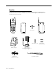
Parts List Along with this book and the MDW 9030P Pocketphone Quick Reference, the box should contain the items shown below. If it does not, call for customer support as described on the inside front cover of this book.
Additional Parts The following parts may be necessary, depending upon your installation. This Kit of Parts is required only when a single (stand-alone) MDW 9030P Pocketphone is installed: Rubber Feet (4) Radio Module 11-foot (3.
Spare Battery and Headset One nickel metal hydride battery pack, which provides up to 3 hours of talk time, comes with your MDW 9030P Pocketphone. For extended phone usage, you should purchase an additional battery pack. You can store the extra battery pack in the Spare battery compartment of the battery charger. Then when the battery pack in the handset is low, you can switch battery packs.
Installing the MDW 9030P Pocketphone 2 Important Safety Instructions This book contains instructions related to safety labels on the product: ! The exclamation point within an equilateral triangle is intended to alert the user to the presence of important operating and maintenance (servicing) instructions in the literature accompanying the product. ! WARNING indicates the presence of a hazard that can cause severe or fatal personal injury if the hazard is not avoided.
Guidelines for Safe and Efficient Operation Your wireless telephone is a radio transmitter and receiver. When the phone is turned on, it receives and sends out radio frequency (RF) energy. The phone operates in the frequency range of 902–928 MHz. Your hand-held wireless telephone uses the digital TDD mode. The power is transmitted in bursts at a 200 Hz pulsed repetition rate. The peak envelope transmit power is 325 mW or less.
Basic Safety Precautions for Installation and Use Always follow these basic safety precautions when installing or using this product to reduce risk of injury from fire or electric shock. ! WARNING: Installation of this equipment for In-Range Out of Building (IROB) conditions requires the use of protectors. See the documentation that came with your communications system for more information.
– Installing a new radio module ■ – Connecting or disconnecting telephone line cords – Adding a carrier Use only the type of battery pack shipped with this product. ! WARNING: The rechargeable battery pack may contain elements that are harmful to the environment (for example, nickel). Do not burn or puncture the battery pack. Like other batteries of this type, if it is burned or punctured, it could release toxic material which could cause injury. Do not dispose of it in household garbage.
■ Use only the power supply (Comcode 847224227) shipped with the carrier. ■ Use only the correct power source. If you are not sure of the power supply to your location, consult your local power company. ■ This product uses a 3-prong plug. Such plugs are designed for your safety. Do not attempt to defeat this purpose. If your wall outlet will not accept the plug, the outlet should be replaced by an electrician.
Radio Modules and Carriers This section explains how to install radio modules and carriers. You should proceed through this section in the following order: 1. “Key Components” 2. “Positioning a Single Radio Module or Carrier(s)” 3. "Wireless Test Mode" 4. Choose one of the following paths, depending upon which components you are installing: ■ If you are installing a single radio module, go to “Installing a Single Radio Module.
Key Components Each radio module communicates with a corresponding handset. The matching sets are identified by a serial number located on the bottom of the radio module and in the battery compartment of the handset.
A carrier is required when installing two or more MDW 9030P Pocketphones.
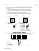
Positioning a Radio Module or Carrier(s) Each of your handsets and its corresponding radio module operates within a single zone of coverage: Approximately 500 to 900 feet in a typical office building; up to 1200 feet in an unobstructed environment POWER RADIO PASS Single Radio Module, Single Carrier, or Multiple Carriers The range depends on your particular operating environment. For indoor use, walls between the handset and the radio module will reduce the phone’s range.
■ ■ ■ ■ The radio module or carrier(s) should not be within 3 feet (.9 m) of any large metal object, and should not have metal objects in the line of sight to the operating area of the handset. The radio module or carrier(s) should not be within 6 feet (1.
Wireless Test Mode You can determine sound clarity, signal strength, and voice quality using Wireless Test Mode. You should use Wireless Test Mode to help you locate the best place to install the radio module(s) to optimize the performance of your MDW 9030P Pocketphone. Repeat the tests several times, with the radio module positioned in a different location each time.
The higher the number, the stronger the signal, as shown in the following table. You can press 1 again to show a subsequent signal-strength reading. Each time you press 1, you get a new reading. Display Number Signal Strength Is 10 Strong 9 Strong 8 Strong 7 Very good 6 Very good 5 Good 4 Good to Fair 3 Fair 2 Near end of range 1 Near end of range/loss of link 7. To determine voice quality, press 2.
Go to one of the following sections: ■ If installing one MDW 9030P Pocketphone, go to “Installing a Single Radio Module.” ■ Otherwise, go to “Setting the Power Level.” Installing a Single Radio Module ■ Install high on wall, leaving 6–12 inches (15.2–30.5 cm) between antenna and ceiling ■ See “Key Components” earlier in this chapter for additional picture detail 1 2 Perform the tests described in "Wireless Test Mode" earlier in this chapter to determine the optimal placement of the radio module.
Insert one end of the telephone line cord into an extension jack or terminal/station connector on your communications system switch/control unit (refer to your communications system manual for the proper location).
Setting the Power Level If you are installing one or more carriers in a strip mall, high-rise office building, or similar environment, the MDW 9030P Pocketphones may interfere with other wireless products in use. ■ If this is the case, you may need to adjust the range of the carriers to prevent overlapping with the other wireless products; follow the instructions in this section. ■ If this is not the case, skip this section and go to “Setting the Control/Expansion DIP Switch.
Use a nonmetallic, pointed object to set each carrier’s DIP switch according to the following table. IMPORTANT: You must set the DIP switch for all of the carriers to the same setting. Desired Range (Approximate) Power DIP Switch Settings O N 500 to 900 feet (152 to 274 m) O N 300 to 500 feet (91 to 152 m) O N 150 to 300 feet (46 to 91 m) O N 100 to 150 feet (31 to 46 m) Go to one of the following sections: ■ If installing multiple carriers, go to “Setting the Control/Expansion DIP Switch.
Setting the Control/Expansion DIP Switch You must follow the instructions in this section if you are installing multiple carriers. Otherwise, skip to “Installing a Single Carrier on a Shelf or Desk” or “Installing a Single Carrier on a Wall.” If you are installing multiple carriers, you must designate one carrier (the leftmost carrier) as the control carrier and the remaining carriers as expansion carriers.
Installing a Single Carrier on a Shelf or Desk ■ You will not receive optimum performance if unit is placed on a desk or low shelf ■ Install as high as possible, leaving 6–12 inches (15.2–30.
5 When the card edge is fully seated, a snap lock on the bottom of the radio module will engage. 6 Insert a telephone line cord into the bottom of each radio module. the telephone line cords through the rear 7 Slide exit slots on the bottom of the carrier. Cords originating from Modules 1 and 6 can share exit slots with cords from Modules 2 and 5 respectively.
9 Insert the carrier’s AC adapter cord into the left O N 1 2 3 10 Place the carrier on its feet towards the back of the shelf or desk, making sure it is in a stable position. Be sure the telephone line cords come out the rear exit slots in the back of the unit. Arrange the power cord and telephone line cords beneath the shelf or desk so no one can step on them or trip over them.
Installing a Single Carrier on a Wall ■ Install high on wall, leaving 6–12 inches (15.2–30.5 cm) between antennas and ceiling ■ Never install or remove a radio module from a carrier that is plugged into a wall outlet (hot insertion) ■ See “Key Components” earlier in this chapter for additional picture detail 1 Perform the tests described in "Wireless Test Mode" earlier in this chapter to determine the optimal placement of the radio module.
5 Starting from the leftmost slot (#1), insert each radio module into the carrier by hooking it onto the radio module mounting rod. Slowly swing the radio module's card edge into the card edge connector on the back of the carrier. When the card edge is fully seated, a snap lock on the bottom of the radio module will engage. 6 7 Insert a telephone line cord into the bottom of each radio module. 8 Slide the telephone line cords through the cable manager slot on the left front of the carrier.
9 Insert the free end of each telephone line cord X N T S E I into the appropriate extension jack or terminal/ station connector on your communications system switch/control unit (refer to your communications system manual for the proper location).
Installing Multiple Carriers ■ Install each carrier high on wall, leaving 6–12 inches (15.2–30.5 cm) between antennas and ceiling ■ Install each carrier 1 foot (0.3 m) optimal to 4 feet (1.
4 Connect an expansion cable to the OUT jack of 6 the control carrier. ION CAUT IN OUT OUT YNC OF S Insert the free end of the expansion cable into 7 the IN jack of the expansion carrier immediately to the right of the control carrier. ION CAUT NOTE: Although installing an expansion cable into the wrong IN or OUT jack will not harm either carrier, doing so causes all handsets to work improperly and the Out of Sync LED to light.
10 Working from left to right, insert a radio module into each slot of the control carrier, starting with Slot 1; hook each radio module onto a mounting rod. Slowly swing the radio module's card edge into the card edge connector on the back of the carrier. IMPORTANT: Slot 6 of a carrier that has another carrier to the right of it must always contain a radio module to pass the synchronization signal to the next carrier.
14 Slide the telephone line cords through the cable manager slot on the left front of each carrier. 15 Insert the free end of the telephone line cord into the appropriate extension jack or terminal/ station connector on your communications system switch/control unit (refer to your communications system manual for the proper location).
18 Plug each carrier’s power cord into one of the following power sources that is not controlled by an on/off switch: ■ Properly grounded 3-prong wall outlets ■ Surge suppressor strip Power the carriers as follows: If the carriers are plugged into... Then... one surge suppressor strip power the strip. Result: All carriers will turn on simultaneously.
Installation Self-Test Upon installation, the POWER and PASS LEDs on each radio module will light. The radio modules then initiate a 2-minute self-test and synchronization. If a radio module’s PASS LED does not light, repower the module or its carrier. Refer to Chapter 5, “Troubleshooting,” if the PASS LED still does not light. NOTE: The RADIO LED also may light upon installation; however, since the RADIO LED has no significance during the self-test, ignore its operation.
Handset This section explains how to install the handset battery pack, change the communications system setting, and fill out the handset label. Inserting and Removing the Handset’s Battery Pack 1 To insert the battery pack into the handset, insert the two small rectangular tabs located along the bottom back edge of the handset into the two rectangular holes along the bottom front edge of the battery pack. Rectangular tabs Press the battery pack downward until it clicks 2 into place.
Changing the Communications System Setting The communications system you use determines what information the MDW 9030P Pocketphone can display and how the phone lines and programmable/intercom/drop buttons are identified (see "Button Mapping" in Chapter 6, "MDW 9030P Pocketphone Compatibility"). The MDW 9030P is factory-set to work with the PARTNER communications system.
Filling Out the Handset Label The MDW 9030P Pocketphone display shows the status of up to 12 lines or programmable/intercom/drop buttons. Since the MDW 9030P is compatible with several different communications systems, diagrams of the button mapping for these systems are provided in Chapter 6.
Battery Charger This section explains how to choose a location for the battery charger and install it. It also explains how to insert and remove a battery pack. Positioning the Battery Charger The battery charger can be placed on a desk, or it can be mounted on a wall. Before you install the battery charger, note the following considerations: ■ Locate the battery charger within 5 feet (1.6 m) of a properly grounded 3-prong electrical outlet that is not controlled by an on/off switch.
5 Insert the battery charger’s power cord/AC adapter into the battery charger. If you are desk-mounting the battery charger, skip to Step 7. 4 Place the keyhole-shaped openings in the back 4 of the battery charger over the screw heads 6 and wall spacers, then slide the battery charger downward into the groove in the wall spacers to lock it into place. the battery charger's power cord/AC 7 Plug adapter into a properly grounded 3-prong wall outlet that is not controlled by an on/off switch.
Inserting a Battery Pack into the Spare Battery Compartment Slide the battery pack into the Spare battery compartment until it is firmly seated with the back of the battery pack against the back of the Spare battery compartment. Do not force the battery pack down. The battery pack should slide easily into the slot. Correct positioning of the battery pack in the charger is important to ensure proper charging.
Inserting the Handset into the Battery Charger's Handset Cradle Correct positioning of the handset in the charger is important to ensure proper charging. 1 Position the handset (with its battery pack attached) so that the two small round holes in the bottom of the handset fit over the two guide pins on the bottom of the handset cradle. 2 Rock the handset back into the cradle until it is firmly seated with the back of the handset battery pack against the back of the handset cradle.
Using the MDW 9030P Pocketphone 3 Important Safety Instructions Please see "Important Safety Instructions" at the beginning of Chapter 2. The Handset This section describes the handset and how to use it. It also explains how to use a headset.
Handset Controls Receiver Headset On/Off Receives the sound of your caller's voice, unless a headset is connected. Press to turn the headset on if the headset is plugged in. ON appears in handset display. To turn off, press again. Turn on to make or answer a call, and turn off to “hang up.” Antenna Extend fully or retract fully to use handset. Extend fully to maximize the handset range and voice quality. Lanyard Loop Attach lanyard for carrying handset.
Column and Select Buttons The MDW 9030P Pocketphone can display the status of up to 12 lines or programmable/ intercom/drop buttons; however, it has only 4 selection buttons (the Column buttons). The Select button (") is used in conjunction with the Column buttons (') to increase the available selections to 12. Each Column button (') affects one of the three lines or programmable/intercom/drop buttons directly above it, as shown in the illustration below.
Handset Display The MDW 9030P Pocketphone display has one 16-alphanumeric-character line, and four lines of icons to provide you with status information. 3 4 5 6 1 MSG RANGE ON 2 8 MUTE 7 9 Note: This illustration is intended to show you what all of the indicators look like, but you will never see all of the line status indicators illuminated at once.
Display Messages The top line of the handset display uses up to 16 alphanumeric characters to provide messages such as the following: ■ LCL:P (or LCL:D, LCL:M1, or LCL:M2) indicates that the handset is in Local Mode, and tells which communications system the button mapping is set to emulate: PARTNER systems DEFINITY systems, System 25, System 75, and System 85 All MERLIN systems (except MERLIN 410 and MERLIN 820), including MERLIN LEGEND LCL:M2 MERLIN 410 and MERLIN 820 WIRELESS TEST indicates that the han
Range Indicators For maximum range and voice quality, always fully extend the antenna before placing or answering a call. The antenna must be either fully retracted (for short range) or fully extended (for maximum range) to use the Pocketphone. The handset provides an audible and a visual signal to alert you when the handset is near the end of the range of the radio module.
Volume Control To increase or decrease the volume of the handset alerter or the receiver (earpiece): ■ Alerter: Press the “+” or the “–” button while the MDW 9030P is awake but turned off. If the display is dark (the phone is in "sleep" mode), press " to wake it up, then press the “+” or the “–” button. ■ Receiver: Press the “+” or the “–” button while the MDW 9030P is turned on.
Antenna The MDW 9030P Pocketphone comes with a user-replaceable, flexible, retractable antenna. For maximum range and voice quality, always fully extend the antenna before placing or answering a call. You can receive a call (if you are within range of the radio module) without extending the antenna, but you may get a RANGE indication. The antenna must be fully extended for optimal performance.
Enabling or Disabling the Vibrator The vibrator vibrates to alert you to an incoming call in situations where you do not want to disturb others with an audible ring. You can enable or disable the vibrator using the following procedure: 1. Make sure the handset is turned off. 2. Press and hold the Select button (") for three seconds. 3. While still holding ", press O. The handset beeps twice, and the display shows the handset settings, indicating that you are now in Local Mode.
To enable Line Preselection, use the following procedure: 1. Make sure the handset is turned off. 2. Press and hold the Select button (") for three seconds. 3. While still holding ", press O. The handset beeps twice, and the display shows the handset settings, indicating you are in Local Mode. (While in Local Mode, the MDW 9030P can still receive notification of incoming calls.) If Line Preselection is enabled, PSEL shows on the top line of the display.
Enabling or Disabling the Alerter The alerter is an audible signal to notify you of an incoming call. If a call comes in while the phone is idle, the handset rings. If you are already on a call, the handset chirps softly. You can adjust the volume of the alerter by pressing the "+" button or the "–" button on the side of the handset when the phone is turned off. You can enable or disable the alerter using the following procedure: 1. Make sure the handset is turned off. 2.
Test Modes You can use Local Test Mode and Wireless Test Mode to verify that your handset is working properly and that the MDW 9030P system is performing optimally.
Using Wireless Test Mode You can determine sound clarity, signal strength, and voice quality using Wireless Test Mode. You can also use Wireless Test Mode to identify which radio module matches your handset. NOTE: Ignore anything that displays if you press 4 or 5 while in Wireless Test Mode. These displays are for Lucent Technologies technicians’ use only. To identify the matching radio module for your handset, use the following procedure: 1. Make sure the handset is turned off. 2.
Performance/Range Test in Wireless Test Mode Using the signal-strength test and the voice-quality test together, you can determine the range in which your MDW 9030P Pocketphone performs best at your site: At 10–15 feet (3.1–4.6 m) from its radio module, use the following procedure: 1. Make sure the handset is turned off. 2. Press and hold the Select button (") for three seconds. 3. While still holding ", press O.
"Waking Up" the Phone In addition to "On" and "Off," the MDW 9030P has an energy-saving "sleep" or "standby" mode. The MDW 9030P "goes to sleep" 15 seconds after activity ceases (that is, after an alert stops ringing or after you hang up). The O and " buttons "wake up" the phone. The headset and handset O buttons turn the phone on, and the Select button (") signals the phone that activity is occurring.
Manually Selecting a Line or Programmed Button When you are making or answering a call, the MDW 9030P automatically selects the line for you. In some situations, however, you may want to select a particular line (for example, to use an "800" line). To select a particular line or programmable/intercom/drop button, use the following procedure: 1. Press O. The ON icon displays steadily, and you are connected to an available line. 2.
Using a Headset Lucent Technologies offers the Supra 9030 headset, which is specifically designed for use with your MDW 9030P wireless phone. A headset assists in call answering, and provides hands-free operation. For ordering information, see "Ordering Replacement & Optional Parts" in Chapter 4. To use the Supra 9030 headset, hold its cord with the "UP" label facing you, and insert the plug directly into the headset connector on the bottom of the handset (near the mouthpiece).
Placing Calls with a Headset To place a call with a headset: 1. Press the On/Off button near the antenna or the access an available line. O button near the dialpad to The microphone and earpiece in the handset are disabled. 2. Dial the call as you would on a wired system phone. 3. Press either the On/Off button near the antenna or the O button near the dialpad to end the call.
The Battery Charger The battery charger charges battery packs in the Spare battery compartment and in the handset. If both are present at the same time, charging in the Spare battery compartment is suspended until the battery pack in the handset is fully charged. To enable extended phone usage, you should purchase an extra battery pack and store it in the charger, so that you always have a charged battery pack to switch to, if necessary.
The color of the battery charger's LEDs indicates the state of the corresponding battery pack, as shown in the following table: Battery charger LED shows... If it is the SPARE LED, the battery pack in the Spare battery compartment... If it is the HANDSET LED, the battery pack in the Handset... If it is the REFRESH LED, the Refresh button was pressed, and the Handset battery pack...
Extending Battery Life The battery charger will charge a battery pack in the handset if you simply insert the handset in the battery charger's handset cradle; however, the Refresh process fully discharges the battery pack before recharging it, thereby ensuring the best possible charge. "Memory effect" reduces a battery's capacity, and can occur when you repeatedly recharge a battery pack before it is fully discharged.
Follow these steps to ensure an uninterrupted supply of power to your MDW 9030P Pocketphone: ■ If you have only one battery pack, be sure to refresh it at least once a week. You can refresh it by: – Placing it in the Spare battery compartment of the battery charger. – Leaving it in the handset, placing the handset in the handset cradle of the battery charger, and pressing the REFRESH button.
Maintaining the MDW 9030P Pocketphone 4 Impor tant Safety Instr uctions Important Instructions Please see "Important Safety Instructions" at the beginning of Chapter 2. Removing a Radio Module fr om the Car rie from Carrie rierr See “Key Components” in Chapter 2 for additional picture detail. Slot 6 of a carrier that has another carrier to the right of it must always contain a radio module to pass the synchronization signal to the next carrier.
3 Press up and hold the snap lock on the bottom rear of the radio module. Slowly swing the radio module's card edge out of the card edge connector on the back of the carrier, releasing the snap lock when clear. Unhook the radio module from the radio module mounting rod by gently lifting upward. 4 If you removed a radio module from Slot 6 of a carrier that has another carrier to the right of it, you must insert another radio module into this slot.
Verify that the carrier’s Out of Sync LED is not lit. If the LED is lit, power down and then repower the carrier. If the LED is still lit, follow the suggestions in the "Installation Problems" section of Chapter 5, "Troubleshooting." If the LED is still lit, call for help as described on the inside front cover of this book.
Repower the carrier.
Ordering Replacement & Optional Parts To order replacement parts or optional equipment in the continental U.S., call the Sourcebook Sales, Catalog Sales, or National Parts Sales Center toll free. When ordering, please use the part numbers shown in the table below: Item Sourcebook Catalog Sales Sales 1 800 451-2100 1 800 635-8866 National Parts Sales Center 1 800 222-PART MDW 9030P Pocketphone (StandAlone).
Troubleshooting 5 Procedures If you have a problem with your MDW 9030P Pocketphone, you may be able to solve it by following the procedures included in this chapter. If you cannot resolve the problem, call for customer support as described on the inside front cover of this book.
Installation Problems (continued) Symptom Possible Causes Possible Solutions After plugging the radio module or carrier into an electrical outlet, one or more radio module POWER and PASS LEDs do not light. Radio module or carrier(s) is plugged into an electrical outlet controlled by a switch. Plug the radio module or carrier(s) into an outlet not controlled by a switch. Power cord of radio module is not inserted properly.
Installation Problems (continued) Symptom Possible Causes Possible Solutions After plugging the carrier into an electrical outlet, the PASS LED of one or more radio modules does not light. Radio modules are out of synchronization. Power down the carrier and repower it. If you have multiple carriers, repower the control carrier first, and then power the expansion carriers in order from left to right. If the problem persists, call for help.* A radio module is malfunctioning. 1.
Handset Problems Symptom Possible Causes Possible Solutions After pressing O, one or more of the following applies: There is no battery pack in the handset. Insert a battery pack in the handset. Battery pack is not inserted properly in the handset. Reinsert the battery pack in the handset. Battery pack is not charged sufficiently.
Handset Problems (continued) Symptom Possible Causes Possible Solutions You can hear the party on the other end, but they cannot hear you. MUTE appears in the handset display. The M button was pressed inadvertently. Press M again to turn off the mute feature. When placed in the battery charger's handset cradle, the handset does not turn off. Battery charger is plugged into an electrical outlet controlled by a switch, and the switch is turned off.
Battery Problems Symptom Possible Causes Possible Solutions The Battery icon appears in the handset display. This is normal operation for the MDW 9030P Pocketphone. No action is required. The Battery icon flashes in the handset display and the handset beeps twice. Battery power is low. You have 5 minutes or less of talk time left. Either: ■ Complete your call, turn the handset off, and recharge the battery pack. ■ If you have a fully charged spare battery pack, place your call on Hold.
Voice Quality Problems Symptom Handset voice quality and range are not as good as they were before. Possible Causes A competing radio device (for example, a wireless bar-code scanner) has been installed in the area. Both products are competing for the same air space and will conflict when both are being used. Possible Solutions Place the handset in Wireless Test Mode as described in Chapter 2. If the signal strength and voice quality readings are low, look for a newly installed radio device nearby.
Voice Quality Problems (continued) Symptom Possible Causes Voice quality for calls is The handset antenna is lower than expected. only partially extended. Volume is too low at any setting and there is noise on the line. Your business has two or more wireless phones installed and all handsets seem to have developed interference problems at the same time. 5-8 Troubleshooting Possible Solutions Fully extend the handset antenna. There are environmental limitations.
Voice Quality Problems (continued) Symptom Possible Causes Possible Solutions You are on a call and you hear radio interference when another call rings. Communications system in key mode has all lines set to ring. An incoming call “wakes up” all of the other radio modules at the same time to ring the other phones. Refer to Chapter 6, “MDW 9030P Pocketphone Compatibility,” to reset line ringing options.
Range Problems Symptom Handset voice quality and range are not as good as they were before. Possible Causes Possible Solutions A competing radio device (for example, a wireless bar-code scanner) has been installed in the area. Both products are competing for the same air space and will conflict when both are being used. Place the handset in Wireless Test Mode as described in Chapter 2. If the signal strength and voice quality readings are low, look for a newly installed radio device nearby.
Range Problems (continued) Symptom Possible Causes Possible Solutions Electromagnetic fields are interfering. Look for 110/Volt lines, fuse boxes, circuit breakers, electrical junction boxes, or similar items. Move the carrier or radio module at least 6 feet (1.8 cm) away from the potential interference. There is a large metal object within 3 feet (1.2 m) of the radio module. Move the carrier or radio module at least 3 feet (1.2 m) away from the potential interference.
Range Problems (continued) Symptom Possible Causes Possible Solutions No ring on an incoming call, and RANGE appears in handset display. Handset is out of range of its matching radio module. Move the handset closer to the radio module. While you are talking and walking, the handset beeps and RANGE flashes in the handset display. Handset antenna is not fully extended. Fully extend the handset antenna. You are approaching an out-of-range condition.
Battery Charger Problems Symptom Possible Causes No LEDs on battery charger light. Battery charger is plugged into an electrical outlet controlled by a switch and the switch is turned off. HANDSET LED on Handset is not seated battery charger does not properly in battery light when handset is charger's handset cradle. placed in battery charger. Possible Solutions Plug the battery charger into an outlet not controlled by a switch.
Battery Charger Problems (continued) Symptom Possible Causes Possible Solutions HANDSET LED flashes red. Battery pack is defective. If you have a battery pack in the handset and one in the Spare battery compartment, remove both battery packs from the charger to clear the red flashing LED. Then test each battery pack separately as follows: 1. Place the battery pack in the battery charger’s Spare battery compartment. 2. Wait one minute. If the SPARE LED flashes red, order a new battery pack.
Battery Charger Problems (continued) Symptom Possible Causes SPARE LED on battery charger does not light when the battery pack is placed in Spare battery compartment. The battery pack is not seated properly in Spare battery compartment. Possible Solutions Reseat the battery pack in the battery charger’s Spare battery compartment. The contacts on the battery 1. Verify that there are no obstructions on the battery pack or in the Spare pack or battery charger battery compartment are contacts. dirty. 2.
Battery Charger Problems (continued) Symptom Possible Causes SPARE LED flashes red. Battery pack is defective. Possible Solutions If you have a battery pack in the handset and one in the Spare battery compartment, remove both battery packs from the charger to clear the red flashing LED. Then test each battery pack separately as follows: 1. Insert the battery pack in handset and place the handset in the battery charger’s handset cradle. 2. Wait one minute.
MDW 9030P Pocketphone Compatibility 6 Programming and Call Handling Instructions The MDW 9030P Pocketphone can display the status of up to 12 telephone lines, but the number of lines supported by compatible communications system switches varies.
NOTE: The MDW 9030P Pocketphone is fully compatible with the PARTNER family of communication systems. For the remaining communications systems, however, you must carefully note the functional differences between your wireless phone and the phone type identified in the table on the previous page. Differences are summarized on the following pages. Some systems do not support display features. In these cases, the display is not available; the MDW 9030P works as a nondisplay set.
Communications System Compatibility This section describes some communications-system-dependent programming to help you optimize the performance of your MDW 9030P Pocketphone. It also describes how the buttons on a wired phone for your communications system map to the buttons on your MDW 9030P.
Setting the Line-Ringing Options Use the following guidelines to ensure optimal voice quality when using MDW 9030P Pocketphones with a PARTNER, PARTNER Plus, or PARTNER II system in key mode: Telephone System with Two Carriers Communications (one control and one expansion System carrier) System with Three Carriers (one control and two expansion carriers) PARTNER Not applicable: PARTNER supports up to 12 phones. 1.
MERLIN Systems ■ On MERLIN II and MERLIN LEGEND systems, you must connect your wireless phone to an available jack on either a 408 outside line/analog telephone module or a 008 analog telephone module. ■ Since the MDW 9030P does not have a speaker function, the Voice Announce feature must be disabled. It is recommended that you use MERLIN 206/410/820 systems installed with Feature Package 2 with your wireless phone, so that you can disable that feature.
Button Mapping for MERLIN Systems except MERLIN 410 and MERLIN 820 On all MERLIN systems, the MDW 9030P emulates a Model BIS-22D phone (Apparatus Code 7315H). However, the BIS-22D button assignments differ depending on the MERLIN system used. Following is a diagram of the BIS-22D button assignments and the corresponding assignments on the MDW 9030P for all MERLIN systems except MERLIN 410 and MERLIN 820. (See the next section for button mapping for MERLIN 410 and MERLIN 820 systems).
Button Mapping for MERLIN 410 and MERLIN 820 Systems Following is a diagram of the button assignments on a BIS-22D phone used for MERLIN 410 and 820 systems, and the corresponding assignments on the MDW 9030P Pocketphone. (See the previous section for button mapping for all other MERLIN systems, including MERLIN LEGEND systems).
Setting the Line Ringing Options Use the following guidelines to ensure optimal voice quality when using MDW 9030P Pocketphones with MERLIN, MERLIN Plus, and MERLIN II: Telephone System with Two Carriers (one Communications control and one expansion System carrier) System with Three Carriers (one control and two expansion carriers) MERLIN, MERLIN II, MERLIN Plus 1. Set Line Ringing for each extension that has a radio module in the control carrier to Ring. 2.
System 25, System 75, System 85, and DEFINITY Systems ■ This phone must be administered as a BIS-22D MERLIN set (Apparatus Code 7315H) for the following systems: — System 25 — System 75—R1V1, R1V2, and R1V3 — System 85—R2V1, R2V2, R2V3, and R2V4 — DEFINITY G1 (R1V4) — DEFINITY G2—G2.1 and G2.2—(R2V5, R2V6) — DEFINITY G3 Version 1 (R1V5) — DEFINITY G3 Version 1.1 and Version 2 Native terminal administration is provided in DEFINITY G3 Version 3.
Button Mapping for DEFINITY Systems, System 25, System 75, and System 85 On DEFINITY systems, System 25, System 75, and System 85, the MDW 9030P emulates a BIS-22D phone (Apparatus Code 7315H). Following is a diagram of the BIS-22D button assignment, and the corresponding assignments on the MDW 9030P for DEFINITY systems, System 25, System 75, and System 85.
The following illustrations show in parentheses the MDW 9030P Pocketphone button assignments on Pages 2 and 3 of the STATION Administration screens. The button labeled D on the MDW 9030P Pocketphone display automatically defaults to the button labeled D (Drop) on the 7315H phones.
Setting the Line Ringing Options Use the following guidelines to ensure optimal voice quality when using MDW 9030P Pocketphones with System 25, System 75, System 85, and DEFINITY systems: Telephone System with Two Carriers Communications (one control and one expansion System carrier) System 25, System 75, System 85, DEFINITY Systems System with Three Carriers (one control and two expansion carriers) 1. Set Line Ringing for each 1.
Warranty and Repair Information A Lucent Technologies Limited Warranty and Limitation of Liability Lucent Technologies warrants to you, the customer, that your wireless telephone system will be in good working order on the date Lucent Technologies or its Authorized Dealer delivers or installs the system, whichever is later (“Warranty Date”).
■ Abuse, misuse, or negligent acts or omissions of the customer and persons under the customer’s control; or ■ Acts of third parties and acts of God. LUCENT TECHNOLOGIES’S OBLIGATION TO REPAIR, REPLACE, OR REFUND, AS SET FORTH ABOVE, IS YOUR EXCLUSIVE REMEDY. EXCEPT AS SPECIFICALLY SET FORTH ABOVE, Lucent Technologies, ITS AFFILIATES, SUPPLIERS, AND DEALERS MAKE NO WARRANTIES, EXPRESS OR IMPLIED, AND SPECIFICALLY DISCLAIM ANY WARRANTIES OF MERCHANTABILITY OR FITNESS FOR A PARTICULAR PURPOSE.
Post-Warranty Repairs If you purchased the system from Lucent Technologies and you have a post-warranty service contract, Lucent Technologies service is provided under the terms of that contract. To significantly reduce unexpected repair costs after the warranty period, you can purchase a post-warranty service contract from Lucent Technologies.
Regulatory Information B This appendix contains information about the Federal Communications Commission and Industry Canada. FCC Part 15 Rules The Lucent Technologies MDW 9030P Wireless Pocketphone has been tested and has been found to comply with FCC Part 15 Rules. These specifications are designed to provide reasonable protection against harmful interference in a commercial or residential installation.
Specifications C GENERAL Model: MDW 9030P Wireless Pocketphone Dimensions and Weights: Handset Handset w/Battery Pack Battery Charger (BC) 0.45 kgs Battery Charger w/ Battery Pack 0.33 0.15 0.55 0.25 lbs kgs lbs kgs 9.75"(L) x 5.13"(H) x 3.94"(W) 1.00 lbs 24.77 x 13.03 x 10.01 cm 9.75"(L) x 5.13"(H) x 3.94"(W) 24.77 x 13.03 x 10.01 cm 1.22 lbs 0.55 kgs Battery Pack 3.0"(L) x .75"(H) x 2.5"(W) 7.6 x 1.9 x 6.35 cm 0.22 lbs 0.10 kgs Headset w/Cord (approx.) 10.5"(L) x 1.2"(H) x 5.6"(W) 26.
GENERAL (continued) Electrical Handset Specifications: Battery Charger (BC) (Power) Radio Module (RM) Carrier (CA) w/6 RMs 1.0 watt 15 watts 4.0 watts 24.0 watts Battery Pack Life: Power Supply (BC) Power Supply (RM) Power Supply (CA) Nickel Metal Hydride 15 watts (10V 1.5 A) 6.0 watts (10V 600mA) 30.
Index A C Alerter 3-4, 3-7, 3-11 Alerter icon 3-4 Answering a call 3-15, 3-17 Antenna 3-2, 3-6, 3-8 replacement 4-4, 4-5 Call handling 6-1 Carrier compatibility 1-2 control 2-16, 2-23 expansion 2-16, 2-23, 2-24 illustration 1-5, 2-7 installation multiple carriers 2-7, 2-16, 2-23 single carrier on shelf or desk 2-17 single carrier on wall 2-20 positioning 2-8 power supply 2-4, 4-5 powering multiple 2-27 powering single 2-19, 2-22 removing a radio module from 4-1 replacement 4-5 Carrying case 3-7, 4-5 Car
E I Electrical requirements 2-4, C-2 Environmental requirements 2-2, C-1 Expansion cable 2-7, 2-24 Expansion carrier 2-16, 2-23, 2-24 Extension labels 2-31 Extensions, changing 4-3 Icons 3-4 Illustrations battery charger 1-4, 2-34, 3-19 carrier 1-5, 2-7 handset 1-4, 3-2 headset 1-6 radio module 1-4, 2-6 Installation battery charger 2-32 multiple carriers 2-7, 2-16, 2-23 problems 5-1 remote location 2-9 requirements 2-8, C-1 rules 2-8 self-test 2-28 single carrier on shelf or desk 2-17 single carrier on w
Line selection 3-2, 3-3, 3-5, 3-16 Line status 3-4, 3-5 Local Mode 3-5, 3-8 Local Test Mode 3-12 M Making a call 3-15, 3-18 MAP 3-5 MDW 9000 1-1 MDW 9010 1-1 Memory effect 3-19, 3-21 MERLIN systems 1-1, 2-30, 3-5, 6-1, 6-2, 6-5 Message icon 3-4 Microphone 3-2, 3-4, 3-17 Mode Button Mapping 2-30, 3-5 Local 3-5, 3-8 Preselection 3-5, 3-9 Wireless Test 2-10, 3-5, 3-13 MSG icon 3-4 Mute button 3-2 icon 3-4, 5-5 N NO LINK 3-5 No Ring icon 3-4, 3-11 O ON icon 3-4, 3-16 On/Off buttons 3-2, 3-15, 3-17, 3-18 Orde
Replacement parts 4-5 Rules for installation 2-8 S Safety precautions 2-1 Security 1-3 Select button 3-2, 3-3, 3-15, 3-16 Selection rectangle 3-2, 3-3, 3-4, 3-16 Self-test, installation 2-28 Serial number 1-1, 2-6 Signal strength 2-10, 3-14 Sleep mode 2-35, 3-4, 3-15, 3-16 Sound clarity 2-10 Spare battery compartment 2-34, 3-19, 3-21, 5-13 Spare battery pack about 1-6, 3-6, 3-21 inserting/removing from the battery charger 2-34 SPARE LED 2-34, 3-19, 3-20, 5-15, 5-16 Specifications C-1 Standby time 3-21, C-2
✃ Battery Charger Wall-Mounting Template Use the template below to position the screws for mounting your MDW 9030P Pocketphone battery charger: 1. Cut out the template along the dotted line. 2. Lightly affix the template to the wall with tape where you want to attach the battery charger. If possible, choose a location that will position at least one of the screw holes over a wall stud. 3. Mark the wall. 4.
Lucent Technologies 503-801-160 Comcode 107972010 Issue 2 March 1997