
Stereo System User Manual


DEFINITY AUDIX System Release 4.0
System Description Pocket Reference
585-300-214
Issue 1
May 1999
Design and Operation
2-12
Operating Requirements
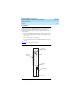
Ta b l e 2 - 2 shows the system’s physical dimensions.
Power Requirements
The DEFINITY AUDIX system draws its power from the 5 volt and -48 volt
buses on the switch’s backplane. Tab le 2 - 3
shows the power the
DEFINITY AUDIX system requires from the switch.
Environmental Requirements
The switch and the DEFINITY AUDIX system generate heat as they
operate. If the operating environment for the system and the switch is
not properly ventilated, this heat can cause these systems to
malfunction. Their operations can also be affected by other
environmental conditions, such as humidity and air quality.
Switch documentation identifies specific guidelines for the switch’s
operating temperature and environment. Generally, the customer should
use these guidelines for creating a suitable operating environment for
the DEFINITY AUDIX system and protecting the system from harmful
environmental conditions. The following guidelines represent the
recommended environmental conditions for DEFINITY switch Release
7.1 and DEFINITY AUDIX system Release 4.0. See the system
description for the customer’s switch for more information about
environmental requirements.
Table 2-2. Physical Dimensions for the DEFINITY AUDIX System
Slots the system
occupies
Height
(Inches)
Width
(Inches)
Length
(Inches)
Weight
(Pounds)
2 7.67 1.44 13.77 3.85
Table 2-3. Power Requirements for the DEFINITY AUDIX System
Switch power source
Maximum power demand from the
DEFINTIY AUDIX system (Watts)
5 volt bus 20
-48 volt bus 11