
Stereo System User Manual

DEFINITY AUDIX System Release 4.0
System Description Pocket Reference
585-300-214
Issue 1
May 1999
Design and Operation
2-6
Hard Disk Drive
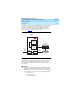
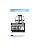
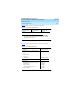
In a DCP Mode 2 connection, the DEFINITY AUDIX system connects to a
DCP port on a TN754 circuit pack. It then connects to an analog port in
the switch’s analog trunk group via a data module and a modem.
Customers can use this connection with any DEFINITY or System 75
switch release. Figure 2-3
shows this connection
Figure 2-3. DCP Mode 2 Connection
Other DCP Mode 2 connections may be available for switch releases
earlier than 7.1. See
DEFINITY AUDIX System — Digital Networking
,
585-300-534, for more information about DCP Mode 2 connections in
these switches.
!
CAUTION:
Operating the DEFINITY AUDIX system in a DCP Mode 2 Digital
Networking connection with higher numbers of subscribers will
significantly degrade the system’s performance. The configuration
for a DCP Mode 2 connection cannot exceed the following limits:
— 10 remote nodes
— 100 local subscribers
— 1000 remote subscribers
DEFINITY
system
cydxsl14 KLC 012299
M7U null
modem cable
Data module
Modem
Analog
T/R
DCP
Analog
port
Analog
trunk
Central
Office
trunk
Digital line
circuit
pack
DEFINITY
AUDIX
system