DEFINITY® AUDIX® System Release 4.0..
Copyright 1999, Lucent Technologies All Rights Reserved, Printed in U.S.A. Notice Every effort was made to ensure that the information in this book was complete and accurate at the time of printing. However, information is subject to change. Your Responsibility for Your System’s Security Toll fraud is the unauthorized use of your telecommunications system by an unauthorized party, for example, persons other than your company’s employees, agents, subcontractors, or persons working on your company’s behalf.
Ordering Information Call: Lucent Technologies BCS Publications Center Voice 1 800 457-1235 International Voice 317 322-6791 Fax 1 800 457-1764 International Fax 317 322-6699 Write: Lucent Technologies BCS Publications Center 2855 N. Franklin Road Indianapolis, IN 46219 Order: Document No. 585-300-214 Comcode 108356106 Issue 1, May 1999 For additional documents, refer to the section in “About This Document” entitled “Related Resources.
Contents Contents iv About this Book vii Intended Audiences vii Supported Product Releases vii Special Terminology vii Trademarks viii How to Order Additional Documentation viii How to Comment on This Book viii 1 Features and Compatibility Feature Overview Features for the Customer Organization 1-1 1-1 1-1 Features for the Subscriber 1-2 Features for the System Administrator 1-3 Compatibility 1-4 Switches 1-4 Native and Non-native Mode 1-5 2 Design and Operation TN568 Circuit Pac
DEFINITY AUDIX System Release 4.
DEFINITY AUDIX System Release 4.0 System Description Pocket Reference 585-300-214 Issue 1 May 1999 Intended Audiences vii About this Book This book describes the DEFINITY® AUDIX® system Release 4.0. This book is not intended to replace or modify instructions provided in task-specific documentation for the DEFINITY AUDIX system.
DEFINITY AUDIX System Release 4.0 System Description Pocket Reference 585-300-214 Issue 1 May 1999 Trademarks viii Trademarks This book references the following products trademarked by Lucent Technologies: ■ DEFINITY® ■ INTUITY™ ■ AUDIX® ■ ProLogix™ This book references the following products trademarked by their respective vendors: ■ Windows®, Microsoft Corporation ■ dBASE III PLUS®, Ashton-Tate ■ U.S.
DEFINITY AUDIX System Release 4.0 System Description Pocket Reference 585-300-214 Issue 1 May 1999 Features and Compatibility Feature Overview Chapter 1 — Features and Compatibility With the high-quality voice messaging system DEFINITY AUDIX system Release 4.0, customers don’t have to answers telephones, and they can exchange messages at times when it is unnecessary or inconvenient to talk in person.
DEFINITY AUDIX System Release 4.
DEFINITY AUDIX System Release 4.
DEFINITY AUDIX System Release 4.0 System Description Pocket Reference 585-300-214 Issue 1 May 1999 Features and Compatibility Compatibility ■ The Class of Service feature allows administrators to manage system resources by defining up to 12 categories of subscribers with varying access to system features. ■ The Traffic Reports feature and ADAP allow administrators to effectively track subscribers’ system use, identify where to allocate system resources, and decide when to upgrade hardware.
DEFINITY AUDIX System Release 4.0 System Description Pocket Reference 585-300-214 Issue 1 May 1999 Features and Compatibility Compatibility Table 1-1. 1-5 Considerations for the DEFINTIY AUDIX system Switch releases Considerations for the DEFINTIY AUDIX system All Calls using loopback trunks cannot terminate at the DEFINITY AUDIX system Earlier than 5.3 These switches do not support the use of multifunction analog telephones (MFATs) Earlier than 2g.04.5.0.
DEFINITY AUDIX System Release 4.0 System Description Pocket Reference 585-300-214 Issue 1 May 1999 Features and Compatibility Compatibility Operating in non-native mode does not affect subscribers’ or outside callers’ use of the system. System administrators, however, should be aware that messages from the switch, such as alarms, that refer to a TN754 or a TN2181 circuit pack the system is emulating may actually refer to the DEFINITY AUDIX system.
DEFINITY AUDIX System Release 4.0 System Description Pocket Reference 585-300-214 Issue 1 May 1999 Features and Compatibility Compatibility Table 1-2. 1-7 Switch Releases Compatible with the DEFINITY AUDIX System Compatible switch releases Do these software releases support the system in native mode? System 75 ■ Release 1 Version 3 ■ Release 1 Version 3n No No G1 ■ ■ G1.1 G1.
DEFINITY AUDIX System Release 4.
Issue 1 May 1999 DEFINITY AUDIX System Release 4.
DEFINITY AUDIX System Release 4.0 System Description Pocket Reference 585-300-214 Issue 1 May 1999 Design and Operation TN568 Circuit Pack TN568 Circuit Pack The TN568 circuit pack holds the systems main circuitry and performs system’s main processing functions, including message routing, self-diagnosis, and Alarm Origination. Port Board Emulation The TN568 holds the system’s voice ports. These voice ports correspond to the voice ports on a TN754 or TN2181 circuit pack. DEFINITY switch releases 7.
DEFINITY AUDIX System Release 4.0 System Description Pocket Reference 585-300-214 Issue 1 May 1999 Design and Operation Hard Disk Drive Software AUDIX software allows the DEFINITY AUDIX system to communicate with the switch through a telephone-like interface. This type of operation is called set-type emulation. The commands that subscribers and the switch use to access the system’s software correspond to the interface on a digital telephone, or set.
DEFINITY AUDIX System Release 4.0 System Description Pocket Reference 585-300-214 Issue 1 May 1999 Design and Operation Hard Disk Drive 2-4 Networking features. In its maximum configuration, the DEFINITY AUDIX system can connect through this Digital Networking channel to up to 100 remote systems, or nodes.2 Digital Networking offers several advantages over AMIS Analog Networking: ■ Digital Networking is more secure than AMIS Analog Networking.
DEFINITY AUDIX System Release 4.0 System Description Pocket Reference 585-300-214 Issue 1 May 1999 Design and Operation Hard Disk Drive 2-5 ■ DCP Mode 1 connections transmit data at 56 Kbps. DCP Mode 1 uses a DS1 facility on the switch or a dedicated facility on a T1 carrier. ■ DCP Mode 3 connections transmit data at 64 Kbps. DCP Mode 3 can use a DS1 facility or an ISDN facility on the switch or a dedicated facility on a T1 carrier.
Issue 1 May 1999 DEFINITY AUDIX System Release 4.0 System Description Pocket Reference 585-300-214 Design and Operation Hard Disk Drive 2-6 In a DCP Mode 2 connection, the DEFINITY AUDIX system connects to a DCP port on a TN754 circuit pack. It then connects to an analog port in the switch’s analog trunk group via a data module and a modem. Customers can use this connection with any DEFINITY or System 75 switch release.
Issue 1 May 1999 DEFINITY AUDIX System Release 4.0 System Description Pocket Reference 585-300-214 Design and Operation MO Disk Drive 2-7 MO Disk Drive Customers and Lucent Technologies technicians can use the MO disk drive to back up data at regular intervals, load software when it is necessary, and transfer data during installations, migrations, or system moves.
DEFINITY AUDIX System Release 4.0 System Description Pocket Reference 585-300-214 Issue 1 May 1999 Design and Operation Faceplate 2-8 Faceplate The faceplate covers the DEFINITY AUDIX system’s internal hardware components.
DEFINITY AUDIX System Release 4.0 System Description Pocket Reference 585-300-214 Issue 1 May 1999 Design and Operation On-board Cables For more information about performing maintenance and administration procedures using the faceplate, see Chapter 3 or DEFINITY AUDIX System Release 4.0 — Maintenance, 585-300-121.
Issue 1 May 1999 DEFINITY AUDIX System Release 4.0 System Description Pocket Reference 585-300-214 Design and Operation Operating Requirements 2-10 DEFINITY AUDIX system 4 5 6 7 8 9 10 11 12 13 14 15 16 TN568 circuit pack DUPN INTFC PROCR MEMORY PROCR INTFC NET CONT PACKET CONT TONE DET/GEN TONECLOCK 1 2 EXPN INTFC EXPN INTFC 3 4 5 6 7 8 9 10 11 12 13 14 15 16 POWER SUPPLY POWER UNIT scdx568p KLC 021999 Figure 2-6.
DEFINITY AUDIX System Release 4.0 System Description Pocket Reference 585-300-214 Issue 1 May 1999 Design and Operation Operating Requirements 2-11 Empty space Slot 6* TN568 DEFINITY AUDIX system MAJ RED EMER XFER ON AMBER CARD IN USE EM XFR MIN ON AUTO OFF scdxcmc KLC 022299 T N 7 9 8 B T N 2 1 8 2 B *The DEFINITY AUDIX system only requires one slot in the CMC if it is installed in slot 6 Figure 2-7.
Issue 1 May 1999 DEFINITY AUDIX System Release 4.0 System Description Pocket Reference 585-300-214 Design and Operation Operating Requirements 2-12 Table 2-2 shows the system’s physical dimensions. Table 2-2. Physical Dimensions for the DEFINITY AUDIX System Slots the system occupies Height (Inches) Width (Inches) Length (Inches) Weight (Pounds) 2 7.67 1.44 13.77 3.85 Power Requirements The DEFINITY AUDIX system draws its power from the 5 volt and -48 volt buses on the switch’s backplane.
DEFINITY AUDIX System Release 4.0 System Description Pocket Reference 585-300-214 Issue 1 May 1999 Design and Operation Operating Requirements 2-13 Table 2-4 shows the system’s atmospheric requirements. Table 2-4. Atmospheric Requirements Temperature1 (° F) Relative humidity (%) Air pressure (psi) 65 to 85 20 to 60 9.4 to 15.2 1. For customer sites at altitudes above 5000 feet, subtract 1°F from the maximum temperature for every 1000 feet over 5000.
DEFINITY AUDIX System Release 4.
Issue 1 May 1999 DEFINITY AUDIX System Release 4.0 System Description Pocket Reference 585-300-214 Capacity and Sizing 3-1 Voice Ports Chapter 3 — Capacity and Sizing Lucent Technologies configures the DEFINITY AUDIX system’s capacity according to the customer’s requirements for the system’s resources. Customers are divided into two categories of system use: ■ Basic usage customers use the DEFINITY AUDIX system mainly for call coverage.
Issue 1 May 1999 DEFINITY AUDIX System Release 4.0 System Description Pocket Reference 585-300-214 Capacity and Sizing Voice Ports 3-2 The system’s GOS represents the fraction of calls to the port group that are delayed more than 10% of the length of an average session during the busiest hour of the day. Session times vary with subscribers’ feature use, but session times average 60 to 100 seconds when all subscribers access features through a single port group.
DEFINITY AUDIX System Release 4.0 System Description Pocket Reference 585-300-214 Issue 1 May 1999 Capacity and Sizing Voice Ports Understanding the port capacities for the DEFINITY AUDIX system Release 4.0 will help customers decide which port packages are right for their organizations’ needs. Features that Affect Voice Ports Some of the DEFINITY AUDIX system’s features can place varying demands on the system’s resources.
DEFINITY AUDIX System Release 4.0 System Description Pocket Reference 585-300-214 Issue 1 May 1999 Capacity and Sizing Voice Storage Digital Networking Using Digital Networking reduces the system’s maximum number of voice ports from 12 to 8. Customers who need Digital Networking and more than 8 voice ports should consider using an INTUITY messaging system. For more information about the INTUITY messaging system, see INTUITY Messaging Solutions.
DEFINITY AUDIX System Release 4.0 System Description Pocket Reference 585-300-214 Issue 1 May 1999 Capacity and Sizing INTUITY Message Manager 3-5 The DOSS configurator allots two hours of voice storage space for each audible language set or three hours of space for the Telecommunications Device for the Deaf (TDD) announcement set. Table 3-3 shows the number of language sets the system can hold, given its voice storage capacity minus a two-hour allowance for each language set.
DEFINITY AUDIX System Release 4.0 System Description Pocket Reference 585-300-214 Issue 1 May 1999 Capacity and Sizing Backup Limits on the MO Disk Table 3-4. 3-6 Limits for INTUITY Message Manager System activities Limits User activities Administered subscribers Limits of the DEFINITY AUDIX system None TCP/IP sessions 0 to 500 Subscribers receive notification of new messages arriving in their AUDIX mailboxes Login sessions 0 to 32 Audio sessions 1.
DEFINITY AUDIX System Release 4.0 System Description Pocket Reference 585-300-214 Issue 1 May 1999 Transition Notes System Design Appendix A — Transition Notes The hardware design for DEFINITY AUDIX system Release 4.0 has changed significantly from previous releases of the system. The most important result of these changes is a 60% reduction in the space the system requires in the customer’s switch.
DEFINITY AUDIX System Release 4.0 System Description Pocket Reference 585-300-214 Transition Notes System Design While DEFINITY switch Version 4, Version 5, and Release 6 recognized earlier DEFINITY AUDIX system releases’ TN566 or TN567 circuit packs as belonging to the DEFINTY AUDIX system, these switch releases will recognize DEFINITY AUDIX system Release 4.0’s TN568 circuit pack as a TN754 or TN2181 digital port circuit pack.
DEFINITY AUDIX System Release 4.0 System Description Pocket Reference 585-300-214 Transition Notes System Design must administer the maximum number of voice ports the DEFINITY AUDIX system will allow.3 If the DEFINITY AUDIX system emulates a TN754 8-port circuit pack, the administrator or technician will need to administer 8 voice ports.
DEFINITY AUDIX System Release 4.0 System Description Pocket Reference 585-300-214 Transition Notes System Design information about the INTUITY messaging system, see INTUITY Messaging Solutions. Alarm Origination In addition to the TN566 or TN567 multifunction circuit pack, previous releases of the DEFINITY AUDIX system used a secondary circuit pack, called an alarm board .
DEFINITY AUDIX System Release 4.0 System Description Pocket Reference 585-300-214 Transition Notes System Design information about modem initialization strings, see Installation and Switch Administration for the DEFINITY AUDIX System Release 4.0, 585-300-122. Alarm Relay Previous releases of the DEFINITY AUDIX system could use the two-wire alarm relay to notify INADS of major alarms.
DEFINITY AUDIX System Release 4.0 System Description Pocket Reference 585-300-214 Transition Notes Switch Integration Switch Integration In most switches, the DEFINITY AUDIX system operates in a mode called display set integration. In display set integration, the DEFINITY AUDIX system communicates with subscribers’ telephones to perform such actions as lighting MWIs and recording callers’ names and extensions. The four main chapters of this book focus solely on display set integration.
DEFINITY AUDIX System Release 4.0 System Description Pocket Reference 585-300-214 Transition Notes Switch Integration Limited Availability for Control Link Integration DEFINITY AUDIX system Release 4.0 will only operate in control link integration if the customer has a PI or PGATE circuit pack. The CMC does not support PI or PGATE circuit packs.
DEFINITY AUDIX System Release 4.
DEFINITY AUDIX System Release 4.0 System Description Pocket Reference 585-300-214 Issue 1 May 1999 Customer Responsibilities B-1 Staff Appendix B — Customer Responsibilities During implementation—the process that drives the DEFINITY AUDIX system’s purchase and installation—Lucent Technologies staff will help ensure the DEFINITY AUDIX system meets the customer’s voice messaging needs. They will install the system and provide maintenance support once the system up and running.
DEFINITY AUDIX System Release 4.0 System Description Pocket Reference 585-300-214 Customer Responsibilities Environmental Requirements B-2 Switch documentation identifies specific guidelines for the switch’s operating environment. Generally, the customer should use these guidelines for creating a suitable operating environment for the DEFINITY AUDIX system. The following guidelines represent the recommended environmental conditions for DEFINITY switch Release 7.1 and DEFINITY AUDIX system Release 4.0.
DEFINITY AUDIX System Release 4.0 System Description Pocket Reference 585-300-214 Customer Responsibilities Cable Connections Table B-2. B-3 Air Purity Requirements Contaminant Total particulate matter, including the following: Average concentration 185.00 microgram/m3 Dust Lint Carbon particles Paper fiber Metal fragments Nitrate in particulate matter 12.00 microgram/m3 Corrosive gases Total hydrocarbons equivalent to methane 10.00 ppm Sulphur dioxide 0.20 ppm Oxides of nitrogen 0.
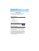
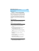
DEFINITY AUDIX System Release 4.0 System Description Pocket Reference 585-300-214 Issue 1 May 1999 Customer Responsibilities Cable Connections DEFINITY system B-4 DEFINITY AUDIX adapter cable TN568 circuit pack Customer-provided power source RS-232 cable Power cord To wall field Customerprovided modular cord Modem External modem connector cydxsl12 KLC 111798 Figure B-1.
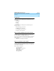
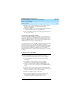
DEFINITY AUDIX System Release 4.0 System Description Pocket Reference 585-300-214 Issue 1 May 1999 Customer Responsibilities Cable Connections B-5 8 7 6 5 4 3 2 1 8 7 6 5 4 3 2 1 104A h2dx104p KLC 021999 WE Lucent-provided D8W cord RJ-45 connectors 10BaseT Customer-provided LAN connection To DEFINITY AUDIX LAN connector Figure B-2.
DEFINITY AUDIX System Release 4.
DEFINITY AUDIX System Release 4.
DEFINITY AUDIX System Release 4.
DEFINITY AUDIX System Release 4.
DEFINITY AUDIX System Release 4.
DEFINITY AUDIX System Release 4.
DEFINITY AUDIX System Release 4.
DEFINITY AUDIX System Release 4.0 System Description Pocket Reference 585-300-214 Issue 1 May 1999 Glossary GL-1 Glossary Numeric 10BaseT A network baseband medium using twisted pair wire, operating at 10 Mbits per second. A Activity Menu The list of main options voiced to subscribers when they access the DEFINITY AUDIX System. Administration The process of setting up a system (such as a switch or a voice mail system) so that it will function as desired.
DEFINITY AUDIX System Release 4.0 System Description Pocket Reference 585-300-214 Issue 1 May 1999 Glossary GL-2 Asynchronous Transmission A form of serial communications where each transmitted character is bracketed with a start bit and one or two stop bits. Asynchronous Data Unit (ADU) A small device that can extend data transmission far beyond recommended Electronic Industries Association (EIA) limits over building wiring.
DEFINITY AUDIX System Release 4.0 System Description Pocket Reference 585-300-214 Issue 1 May 1999 Glossary GL-3 Boot Filesystem The filesystem from which the system loads its initial programs. Broadcast Messaging A feature that enables the system administrator and other designated users to send a voice mail message to all subscribers automatically. Buffer Memory used to compensate for time differences in transmission by temporarily storing data.
DEFINITY AUDIX System Release 4.0 System Description Pocket Reference 585-300-214 Issue 1 May 1999 Glossary GL-4 Command Mode A system state in DEFINITY AUDIX system releases earlier than 4.0 where flashware is in control and software is shut down. In this state, a technician has access to menu options to see flashware status and initialization history, run through flashware diagnostics, and to start or continue system initialization.
DEFINITY AUDIX System Release 4.0 System Description Pocket Reference 585-300-214 Issue 1 May 1999 Glossary GL-5 Digital-Port (DP) Mode The type of switch-link integration for which the DEFINITY AUDIX System, up through release 3.1, is connected to the switch via digital port board emulation. The type of port board that the DEFINITY AUDIX emulates within the switch (TN754.) Digital-Port (DP) Board Emulation In R3.
DEFINITY AUDIX System Release 4.0 System Description Pocket Reference 585-300-214 Issue 1 May 1999 Glossary GL-6 Field An area on a form, menu, or report where information can be typed or displayed. Filesystems A collection of related files (programs or data) stored on disk that are required to initialize a DEFINITY AUDIX System and provide full service. Flash programmable read-only memory (FPROM) Hardware on the TN568 that stores the DEFINITY AUDIX system’s flashware.
DEFINITY AUDIX System Release 4.0 System Description Pocket Reference 585-300-214 Issue 1 May 1999 Glossary GL-7 Header Information that the system creates to identify a message. A message header includes the originator or recipient, type of message, creation time, and delivery time. Hunt Group A group of ports on a switch usually administered to search for available ports in a circular pattern. I Initialization The process of bringing a system to a predetermined operational state.
DEFINITY AUDIX System Release 4.0 System Description Pocket Reference 585-300-214 Issue 1 May 1999 Glossary GL-8 Local Area Network (LAN) A short distance data communications network used to link computers and peripheral devices under some form of standard control Local Maintenance Terminal (LMT) A display terminal located near the DEFINITY AUDIX System and the switch. It is temporarily attached to the DEFINITY AUDIX during an on-site service visit.
DEFINITY AUDIX System Release 4.0 System Description Pocket Reference 585-300-214 Issue 1 May 1999 Glossary GL-9 N Native Mode The ability of the switch to recognize the DEFINITY AUDIX as a DEFINITY AUDIX circuit pack. With native mode support, the switch reserves five slots for the DEFINITY AUDIX 3.2 assembly, and two slots for the DEFINITY AUDIX 4.0. Additionally the switch is able to correctly identify the DEFINITY AUDIX board in alarms sent to the services organization.
DEFINITY AUDIX System Release 4.0 System Description Pocket Reference 585-300-214 Issue 1 May 1999 Glossary GL-10 Protocol A set of specific rules, procedures, or conventions relating to forms and timing of data transmission between two devices. R Reboot A system reboot is done to clear major system problems (such as corrupt program memory). It also runs automatically whenever the system is powered up. Also see boot.
DEFINITY AUDIX System Release 4.0 System Description Pocket Reference 585-300-214 Issue 1 May 1999 Glossary GL-11 Standalone Utility A software utility with options that include disk drive initialization, copying files from a generic tape or MO disk onto the customer’s disk, and map partition modification. With release 3.2 and earlier releases the standalone utilities where referred to as standalone tape utilities.
DEFINITY AUDIX System Release 4.0 System Description Pocket Reference 585-300-214 Issue 1 May 1999 Glossary GL-12 V Voice Port An electrical pathway that connects calls between two devices, such as telephones, switches, or voice messaging systems.
DEFINITY AUDIX System Release 4.
DEFINITY AUDIX System Release 4.
DEFINITY AUDIX System Release 4.
DEFINITY AUDIX System Release 4.