
Installation Instructions


Model 117A4 Carrier Installation Instructions Installing Multiple Carriers
Model 117A4 Carrier Installation Instructions
503-801-18040 Issue 2 February 1999
Installation Self Test for Remaining Radio Modules
1
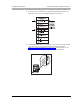
Wait a few seconds after powering the carriers, then verify that the carriers’ OUT
OF SYNC LEDs are not lit.
2
At this stage of your installation, the LEDs displayed should again match the first
or fourth lines of the SYNC and CONTROL/EXP LED Codes label, depending
on whether the carrier is the control or an expansion carrier. (Keep in mind that a
Model 117A3 carrier does not have a CONTROL/EXPANSION LED.)
1 2 3 4
6
4
T
RANS
T
ALK
21
O N
21
O N
5
C
A
U
TIO
N
U
S
E
O
N
L
Y
A
T
&
T
C
A
B
L
E
P
⁄N
8
4
76
6
7
89
6
IN
OUT
O
UT
O
F SYNC
M
N
N
O
E
A
P
T
R
H
A
N
H
A
P
T
E
R
G
R
R
E
P
R
A
C
I
T
E
-
O
K
L
O
R
E
M
I
P
S
U
M
R
E
P
R
A
C
I
T
E
-
O
K
R
E
P
R
A
C
I
T
E
-
O
K
X
E
R
T
F
A
M
R
U
K
L
A
R
I
E
N
L
O
R
E
P
R
A
C
I
T
E
-
O
K
L
O
R
E
M
I
P
S
U
M
X
E
R
T
F
A
M
R
U
K
L
A
R
I
E
N
L
O
OUT OF SYNC
CONTROL/
EXPANSION