
Installation Instructions


Installing Multiple Carriers Model 117A4 Carrier Installation Instructions
Model 117A4 Carrier Installation Instructions
503-801-180
Issue 2 February 1999 23
4
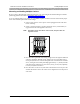
Verify the POWER and PASS LEDs on each radio module are lit. If a radio
module’s PA SS LED does not light, power down the carrier and the module, wait
15 seconds, and repower the module and then the carrier.
Note:
The RADIO LED also may light upon installation; however, since the
RADIO LED has no significance during installation, ignore its operation.
The RADIO LED indicates a connection between the handset and the
radio module; it lights when the handset is being used as long as the
battery pack in the handset is charged.
Installing Multiple Carriers
•
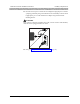
Install each carrier high on wall, leaving 6–12 inches (15.2–30.5 cm) between
antennas and ceiling
•
Install each carrier 1 foot (0.3 m) optimal to 4 feet (1.2 m) from its
neighboring carrier
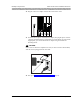
•
Never install or remove a radio module from a carrier that is plugged into a
wall outlet (hot insertion)
Multiple carrier installation involves several stages:
•
Mounting the carriers on the wall and cabling them
•
Installing a single radio module in each carrier
•
Installing the remaining radio modules
The most efficient method for installing carriers and their radio modules is to perform self tests after each stage
of the installation. This enables you to spot any problems at an early stage, and avoid the necessity for
deinstalling the components in order to solve problems.
POWER
RADIO
PASS
Radio
Module
POWER
RADIO
PASS