
User's Manual
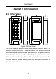

Card Reader
4
Chapter 3 Installation
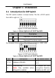
3.1 Introduction for DIP Switch
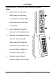
The DIP switch module is shown below. The No. of DIP switch
from left to right is 1 ~ 8.
Figure 3-1 DIP Switch Module
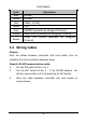
Table 3-1 Description of DIP Switch
Icon
Description
Represent 1 in binary mode
Represent 0 in binary mode
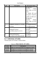
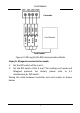
For example, binary value of the following status is: 0000 1100.
Figure 3-2 DIP Switch Module
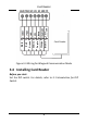
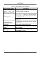
Table 3-2 Description of DIP Switch
No.
Description
DIP Switch Status
1 ~ 4
Address of RS-485
1: 1
0: 0
5
Card Security
Note: Only available when
Wiegand is enabled.
0: Disable M1 card
encryption function,
disable non-M1 card