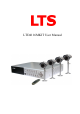
User Manual LTD4116MKIT User Manual 0
User Manual CONTENTS Chapter 1: DVR Features ........................................................................................................................................3 DVR Feature ......................................................................................................................................................3 Chapter 2: Overview ................................................................................................................................................
User Manual Chapter 7: Playback...............................................................................................................................................20 Chapter 8: USB Progamming................................................................................................................................21 8.1Driver Installation: ......................................................................................................................................21 8.
User Manual Chapter 1: DVR Features DVR Feature MPEG-4 compression 4 BNC Camera Inputs - 2 BNC Video Outputs 2 channel Audio Inputs - 2 channel Audio Outputs System Format : NTSC /PAL Motion Detection with Sensitivity and Area Settings Time Schedule, Alarm and Motion Triggered Recording Modes Hard Disk Support up to 500GB Supports PTZ Control via RS-485 Port View and Operate over Network (Broadband Connection Required) Built-in USB 2.0 Port for Backup to Computer Chapter 2: Overview 2.
User Manual 2.2 Rear Panel 1. USB port 2.Audio outputs 3. Audio inputs 4. Video outputs 5. CH1-CH4:video input 1- video input 4 6. LAN: Ethernet port 7.RS485/Sensor/Alarm 8.DC Power Input Jack 9.Power switch 10. Grounding 2.
User Manual Chapter 3: Installation 3.1 Install Hard Disk NOTICE: (1) Don’t take out HDD when DVR is running. Remove the screws around the top cover. (2) Remove the top cover carefully. (3) Connect the power cord and data cable to hard disk carefully. (4) Use the provided screws to fix hard disk on the rack inside and then replace the top cover of the case. 3.2 Connecting Camera and Monitor There are 4 camera inputs and 2 monitor outputs with BNC connectors (Refer to 2.2 Rear Panel). 3.
User Manual 4.2 Detecting Installed Hard Drive DVR will detect the installed hard drive and display the hard drive information. CHECKING HDD…… MASTER [WDC WD3200AAJB-00T] SLAVE…… 4.3 Format Hard Drive CHECKING HDD…… MASTER [WDC WD3200AAJB-00T]-NEW-DVR FORMAT HDD CONFIRM (SELECT) FORMAT / (MENU) CANCEL? When the DVR detects a new hard drive, you will be prompted to format the hard drive before using the DVR. Press [SEL] to format or press [MENU] to cancel. Chapter 5: DVR Menu System 5.
User Manual Menu Directory Camera Setup Record Setup Record Frame rate Video Quality Record Schedule Sensor Setup Main Menu Hard Drive Setup Miscellaneous Setup Network Setup Language Reset Menu 5.3 Camera Setup 1 ON 2 ON CAMERA SETUP 3 ON ( 4 )MOVE ON Change Password Set Time Hidden Channel Audio Port Setup PTZ Setup Image Parameters Password Enable Keypad Tones SEQ.Dwell Time Camera Setup allows you to turn cameras on or off.
User Manual 5.5 Record Frame Rate 1 3FPS 2 RECORD 5FPS FRAMERATE TOTAL 36FPS 3 25FPS ( 4 )MOVE (SEL) + ( 3FPS ■ )- (MENU)EXIT The total frame rate is 50fps (PAL) or 60fps (NTSC). You can set the frame rate for the channel which you selecte to record. If the sum of the frame rate you select for all cameras is more than 50fps (PAL)/60fps (NTSC), the DVR will automatically adjust the largest frame rate value to a smaller value.
User Manual NO-RECORD [ white]: DVR will not record during the time. NORMAL-RECORD [ red]: DVR will record continuously. SENSOR-RECORD [S]: DVR will record when sensor or motion is triggered. NOTE: In order to activate the record schedule, press the [ ] record button when viewing the cameras.
User Manual 5.10 Motion Detector Setup This section allows you to set up motion detection options for each camera. Motion Detector Setup: MOTION CH1 CH2 CH3 CH4 ( DETECTOR ON ON ON ON )MOVE LEVEL1 LEVEL2 LEVEL2 LEVEL2 SETUP AREA AREA AREA AREA (SEL)SELECT (MENU)EXIT ON/OFF: Enable or disable motion detection recording. LEVEL: Sensitivity for motion detection. There are 3 levels sensitivity: Level 1-low, level 3- highest AREA: Select detectable area on the screen.
User Manual HDD FORMAT: Will erase all video and data on the installed hard drive and make it readable by the DVR Note: You will be prompted for the password when formatting a hard drive. The default password is “111111” 5.12 Miscellaneous Setup - Change Password MISCELLANEOUS SETUP CHANGE PASSWORD SET TIME HIDDEN CHANNEL AUDIO PORT SETUP PTZ SETUP IMAGE PARAMETERS PASSWORD ENABLE KEYPAD TONES SEQ.
User Manual 5.14 Miscellaneous Setup - Hidden Channel MISCELLANEOUS SETUP CHANGE PASSWORD SET TIME HIDDEN CHANNEL AUDIO PORT SETUP PTZ SETUP IMAGE PARAMETERS PASSWORD ENABLE KEYPAD TONES SEQ.DWELL TIME ( )MOVE [ 4 ] [ CH4 ] [ OFF ] [ ON ] [OFF] The system provides a function to hide a channel in monitoring mode. The selected channel can still be recorded while it’s hidden; the hidden picture is viewable during playing back. Press [SEL] to select a channel to hide. (SEL)SELECT (MENU)EXIT 5.
User Manual 5.17 Miscellaneous Setup - Image Parameters You can adjust the image parameters MISCELLANEOUS SETUP CHANGE PASSWORD SET TIME HIDDEN CHANNEL AUDIO PORT SETUP PTZ SETUP IMAGE PARAMETERS PASSWORD ENABLE KEYPAD TONES SEQ.DWELL TIME according to your needs. [ 1 Move the cursor to this selection and ] [ CH4 ] [ OFF ] [ ON ] [OFF] press [◄◄] or [►►] button to select a channel you want to adjust, then press [SEL] button to edit parameters.
User Manual 5.19 Miscellaneous Setup - Keypad Tones This function allows you to enable MISCELLANEOUS SETUP /disable buzzer sound when pressing a CHANGE PASSWORD SET TIME HIDDEN CHANNEL AUDIO PORT SETUP PTZ SETUP IMAGE PARAMETERS PASSWORD ENABLE KEYPAD TONES SEQ.DWELL TIME ( )MOVE [ 4 ] [ CH4 ] [ OFF ] [ ON ] [OFF] button. Press [SEL] to select ON or OFF. (SEL)SELECT (MENU)EXIT 5.
User Manual IMPORTANT: This setting should only be changed if multiple DVRs are being setup on the same network and the first code “00” must not to be changed. NETWORK MAC ADDRESS IP ALLOCATION IP ADDRESS SUBNET MASK GATEWAY DNS1 ADDRESS DNS2 ADDRESS HTTP PORT USER SETUP DDNS SETUP SETUP <00:11:22:33:44:55> [STATIC] [192.168.1.100] [255.255.255.0] [192.168.1.1] [0.0.0.0] [0.0.0.0] [ 80] (HTTP PORT) 80, 1024-49151 ( )MOVE SETUP <00:11:22:33:44:55> [STATIC] [192.168.1.100] [255.255.255.0] [192.168.1.
User Manual NOTE: To adjust the IP ADDRESS,SUBNET MASK and GATEWAY value, only when the [STATIC] mode is being selected. NETWORK MAC ADDRESS IP ALLOCATION IP ADDRESS SUBNET MASK GATEWAY DNS1 ADDRESS DNS2 ADDRESS HTTP PORT USER SETUP DDNS SETUP SETUP DNS ADDRESS: This code should be provided by your local ISP. <00:11:22:33:44:55> [STATIC] [192.168.1.100] [255.255.255.0] [192.168.1.1] [0.0.0.0] [0.0.0.
User Manual LAN-DVR Connection See the diagram below for steps to connect your DVR to a local area network or the internet. For remote monitoring from your computer,you must have a LAN connection available or broadband Internet access. You need to register a www.dyndns.com to get a free account .After registration,you will have a username and password. You can also register your domain name on the website. Please refer to Chapter 5 “Network Setup” for more details.
User Manual 5.23 Reset Menu If you select this item, the system will restore all your settings to factory default values. You need to enter your password to reset the menu. 5.24 NTSC/PAL Output select Change the jumper JS1 to select NTSC or PAL video output format according to the silkscreen on the PCB. Chapter 6: Record 6.1 Start Recording Press [●] record button to start recording according to the record schedule you have set. System will display some information on screen.
User Manual recorded. [A-REC]: indicates the current record schedule is set to NORMAL-RECORD mode. [S-REC]: indicates the current record schedule is set to SENSOR-RECORD mode. [N-REC]: indicates the current record schedule is set to NO-RECORD mode. [39%]: indicates the percentage of hard disk space used. [M]: HDD info ([M] Master Hard Disk) 6.2 Audio Recording [ ]: indicates this video channel is bundled with an audio port, and the audio output is on. [ ]: indicates the audio output is off.
User Manual Chapter 7: Playback In preview mode, pressing the [►] PLAY button goes into PLAYBACK mode. The newest record event will be played.
User Manual Chapter 8: USB Progamming 8.1Driver Installation: (1) (2) (3) (4) Insert driver CD in your CD-ROM Drive. Open CD directory. Double click the install applications. Follow the setup wizard to finish the installation. 8.
User Manual 1.PTZ Control 12. Time Search 2.Zoom in,Zoom Out 13.Back One Frame 3.HDD Play Mode 14.Record 4.File Play Mode 15.Stop 5.Net Play Mode 16. Pause 6.Event List 17. Play 7.Control Panel 18.Fast Forward 8.Remote DVR Control 19.Forward One Frame 9.Change Storage Device 20.Playback Slider 10.Capture Image 21.Audio Slider 11.Convert Streams to AVI file 8.3 Program Running 8.3.1 HDD play mode System will detect the HDD automatically when you connect the USB cable to your PC.
User Manual Press “ Press “ ” to configure the program local settings ” to play video. 8.3.2 FILE play mode: (only when you plug a USB Memory Stick into your PC) Press “ ” to open a folder and select the file you want play.
User Manual Double click the file. 8.3.3 NET play mode: This mode allows you to remote control your DVR via Internet or Intranet. Press “ ” to pop up the login window. Fill in Host Name, Host Port, User Name and Password of the DVR that you want remotely access and then press Login to enter the main page.
User Manual Chapter 9: Specification 9.1 DVR Items Descriptions Video Standard NTSC, PAL Video Input/Output 4Channels BNC/2 Channels BNC Audio Input/Output 2 Channels/2 Channels Monitoring Recording Resolution NTSC:720X480@30fps (Each Ch) PAL:720X576@25fps (Each Ch) Features Full-D1,1-CH/4-CH Display Resolution NTSC:720X240@60fps (4Ch.Total) PAL:720X288@50fps (4Ch.
User Manual Chapter 10: Appendix 10.1 System connect sketch map 10.2Accessories Included With DVR Camera cables (4 included) Power Supply USB 2.