Embedded Digital Video Recorder USER MANUAL
>>Stand-alone DVR User Manual CONTENTS Chapter1:Specifications and connector definition····································································3 1.1 Parameter ·····························································································································3 1.2 DVR appearance ··················································································································4 1.
>>Stand-alone DVR User Manual Chapter4 WAN connection···············································································································30 4.1 PPPOE ·······························································································································30 4.
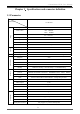
>>Stand-alone DVR User Manual Chapter 1:Specifications and connector definition 1.1 Parameter Model parameter 16 CH DVR Compression H.264 Video source PAL: 400 frame NTSC: 480 frame Video Audio Rec. backup Storage and Network I/O Control way Live resolution D1(704×576) Recording resolution CIF(352×288) Input 16 CH BNC Output 1 CH BNC,1 CH VGA(resolution 1024×768,60Hz) Video standard PAL、NTSC adjustable Audio input 4 CH Audio output 1 CH Compression G.
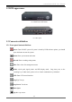
>>Stand-alone DVR User Manual 1.2 DVR appearance Pic.4 Small case with button Pic.5 Rear panel 1.3 Connector definition 1.3.1 Front panel button definition: Power: Turn ON/OFF system. If system is closed by DVR software options, you should press this button to start the system. Menu: Enter system menu and return. Record: Enter recording setting menu. Files: Enter video file management menu.
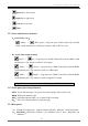
>>Stand-alone DVR User Manual Down: Move down cursor Right: Move right cursor Left: Move left cursor Enter 1.3.2 Panel combination key definition A、ON/OFF key voice: (Mode) + (Back space) : Long time press “Mode” button till you heard “DiDi” sound and then press “Backspace” button to ON or OFF key voice. B、Switch video output channel: (Mode) + (Up):Long time press “Mode” button till you heard “DiDi” sound and then press “Up” button to switch to VGA output.
>>Stand-alone DVR User Manual Pic.6 RS232/485 Pin definition C、 VIDEO 1) Video In:1~16 CH CVBS Video input; 2) Video Out: CVBS Video output。 D、 AUDIO 1) Audio In:1~16CH Audio input; 2) Audio Out:Audio output。 E、 LAN:10/100M network port。 F、 USB:USB2.0 port.
>>Stand-alone DVR User Manual Alarm In 10------------------------------------------------------------------------- 21 Alarm In 11------------------------------------------------------------------------- 8 Alarm In 12------------------------------------------------------------------------- 20 Alarm In 13------------------------------------------------------------------------- 7 Alarm In 14------------------------------------------------------------------------- 19 Alarm In 15---------------------------------
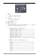
>>Stand-alone DVR User Manual 6. Page Up:Turn up, reduce the number 7. Page Down:Turn down、add the number 8. Menu:Enter main menu / return 9. ESC:Return, exit the operation 10. Mode:Switch quad ,single picture and PIP display mode;Long time press as the switching key of other mode; please refer to “Remote controller combination key definition”. 11. Shift:Switch channel display position. 12. Files:Enter video file management dialog box 13. Information:Check system info 14.
>>Stand-alone DVR User Manual 23. Left:Cursor move left 24. Right:Cursor move right 25. Enter (2) Remote controller combination key definition 1、 (Mode) + (mute) : Long time press “Mode” button till you heard “DiDi” sound and then press “Mute” button to ON or OFF key voice. 2、 (Mode) + direction key(Up, Down, Right):Switch output channel.
>>Stand-alone DVR User Manual insolated or dusty and moist, as well as those places with strong magnetic field or with mechanical shake and strike. ◆ Copyright protection ※ Please don’t infringe the related right of the third party when you make image recording program. ※ Any change or modification on this machine without our permission might destroy the machine and cause many inconvenience to the user. 2.
>>Stand-alone DVR User Manual Alarm input connection 1-N.C. b)Sensor adopt N.O. output contact Alarm input connection 1-N.O. B、 Alarm output connection: Alarm output connection 2.3.3 RS-485/RS485 connection Host have one standard RS-485/232 port, pin definition please refer to Pic.3. RS485 is used to control PTZ decoder and camera, RS232 is used to debugging software and other communications expanding.
>>Stand-alone DVR User Manual 2.4 HDD installation System only supports 2 SATA HDD,and set the jumper on SATA I(Limit to 1.5Gb/s Operation )mode. After that, use bracket to fix the HDD in the DVR, connect the power cable and date cable. 2.5 GND connection After connect the signal cable, please connect the screw with the grand to protect the host. Chapter 3 Operation 3.
>>Stand-alone DVR User Manual 9) Progress Bar 10) Check box :Press left and right key to increase and reduce the value. :choose and press “OK” to confirm it. 11) Radio button :Make a mutually exclusive choice in same list or group. 12) Soft keyboard:press “OK” button in edit box to pop-op soft keyboard. 3.
>>Stand-alone DVR User Manual :Start menu button, press it to bob up start menu. / :Mute ON/OFF button :Video/Audio monitoring status and display mode option / :Login/Lock button :System info button, When alarm incident occurred show alarm status button:“ system backup the data in the background show “ ”。When ” :Time and date setting button 1) Display/Hide In preview status, press any key to display status bar. Press return “ ”or backspace key“ ” to hide it.
>>Stand-alone DVR User Manual Pic.12 User Login b) System Lock On status bar, move the cursor to LOGIN/LOCK icon“ status “ ”,press “OK” to turn into lock ”.In login status, if user do not do any operation in 2 minutes, the system will turn into lock status automatically. 5) SYSTEM INFO On status bar, move the cursor to system info icon“ ”,press “OK” to pop-up the system information checking dialog box.(Refer to “System info” chapter).
>>Stand-alone DVR User Manual host No. match dialog box after “DIDI” two sound, as follow: Input the host number in “Input host No.(0~99)”edit box and press “OK” to confirm. Please refer to the oval box in the picture. Pic.13 Host No 2) Video output channel switch a) Front panel operation:Long time press mode button“ and then press up button“ ” till you heard “DIDI” two sound, ”to choose VGA output, or press down button “ ” to choose CVBS output.
>>Stand-alone DVR User Manual Pic.14 Main Menu 3.61. System Set In “System Set” page, you can set the host name, host number and language. In its sub-menu, you can set system time, recover the factory settings and upgrade the system software. Pic.15 System Set 1) Name:input and amend host name 2) Number:Amend the local host number 3) Language:choose the system language 4) Time set:Presses “Time Set” button to pop-up the time setup dialog.
>>Stand-alone DVR User Manual Pic.16 Time Set 5) FACT.SET: press “FACT. Set” button to pop-up the “recover factory set” dialog. As below: Pic.17 Recover Factory Set After recover factory set, the host number, video format, recording setting parameter etc. will not change. 6) Upgrade:Copy the system upgrade file(*.
>>Stand-alone DVR User Manual 3.6.2 VIDEO SET Set the system video properties; include the output channel, video format, PIP property, video cycle parameter, video channel title, video color parameter. VIDEO SET menu as below: Pic.19 VIDEO SET 1) Video Output:choose output port “CVBS”,press “PGUP” or “PGDW” to choose CVBS、VGA、YUV three output Way. If CVBS output, the resolution bar will be gray, that means disable. If VGA output,the resolution can be:640x480、800x600、1024x768.
>>Stand-alone DVR User Manual Pic.20 Progress bar Press left or right button to adjust parameter values, press UP or DOWN button to switch parameter type, press PGUP or PGDW to switch channel d) e) CH MASK:Select to shield this channel PTZ setting:Enter PTZ setting interface Pic.21 PTZ SET PTZ SET:In this page, you can choose protocol of PTZ which associate with this channel, the baud rate and PTZ ID code. Default PTZ ID code is same as the number of channel that the PTZ associated with.
>>Stand-alone DVR User Manual a) Manual recording: After choose the channel, this channel will start to recording under scheduled parameters (refer to recording parameter setting), and you should manual stop the recording if you need to, the method is to anti-election and confirm it. b) Schedule Recording First you should set the recording time period and then turn on this channel recording. When in scheduled time period, the system will start recording automatically till the time period over.
>>Stand-alone DVR User Manual Pic.24 Alarm set ● Motion: Set video lost alarm, motion detection alarm trigger condition and associated channel. Setting interface as below: 图 25 Video Detect a) Channel No.:Choose the channel that need to be set and the channel title will automatically display in the behind b) Trigger schedule:Set the trigger time periods. c) Alarming Duration:Set the alarm duration.
>>Stand-alone DVR User Manual > Prerecord:Set the prerecord time. After motion detect triggered alarm, > Recording duration:After motion detect triggered alarm, system will on-going record for the set duration time > Area setting:Set the motion detect area. Press setup button to enter the setup interface, as below:: Pic.
>>Stand-alone DVR User Manual Pic.27 Sensor Setting 3.6.5 File Management Manage the recording files,can search, playback and backup the recording files based on the given search condition. Search conditions include channel No., Date type, Record type, Recording date and search periods. Interface as below: Left is date column, the blue background of the date on behalf of the day that has recording files. 1) Recording Search: Input Search channel No., Recording date and search time period.
>>Stand-alone DVR User Manual Pic.29 Video file backup In operation interface, you can choose “play” or “Backup” this file to pointed device. 3.6.6 User Management Create the user account, modify the user’s access, change password etc. Setting interface as below: Pic.30 User management 1) Add/Delete user account: System can manage 8 local accounts. Admin is default administrator account which can not be deleted. Press “Add” button to pop-up user account create dialog box. As Below: Pic.
>>Stand-alone DVR User Manual 2) Change password: Press change password “ ” to popup the changing password dialog box, as below: Pic.32:Change password 3) Authority settings:Charge user’s privilege and press “MODIFY” to confirm it. 3.6.7 NET SET System support LAN、DDNS and PPPOE. Setting interface as below: Pic.33 Network Setting 1) HTTP port set:Set HTTP port, default is 80, If this port changed, when login the host via Web server (IE),The IP address input method is IP add “:”and new port number.
>>Stand-alone DVR User Manual Pic.35 Local Setting a) Obtain an IP automatically: When connected network support DHCP IP(DHCP server open),when you choose “Obtain an IP automatically”,DHCP server will allocate an available IP. System default setting is “Obtain an IP automatically”. b) Manual input IP: System input manual input IP. When choose “Use the following IP address”,IP address filed will be editable, and you can input an IP address ,and then press “OK” to confirm it.
>>Stand-alone DVR User Manual ADSL model via RJ45 or LAN,it will dial automatically or by manual to connect the WAN .PPPOE setting interface as below: Pic.37 PPPOE Setting 3.6.8 Storage Management Manage the storage device, display the device working condition, format and file selection. Interface as below: Pic.
>>Stand-alone DVR User Manual Pic.39:System Information 1) Host Information: Display the host serial No., software version, IP address and MAC address. 2) Link statistics: Press “Link Stat.” to check the customer login information, and you can you can disconnect this IP connection. As below: Pic.40:Link Statistic Above picture tell us the host is connected by two users. It also tells us the visitors IP, port No. and remote monitoring status.
>>Stand-alone DVR User Manual Pic.41:Alarm information 4) System log: Check the host operations recording. Input the date and press “SERACH” to list the operation recording. Pic.42:System Log Left is date column, the blue background of the date on behalf of the day that has operation recording Chapter 4 WAN connection There are two methods to connect the DVR with WAN: one is PPPoE and the other is router forwarding. 4.1 PPPOE Please check relevant chapter. 4.
>>Stand-alone DVR User Manual Set the host IP in “Local setting”,please refer to the chapter “Net set”. Note:Set the “protocol” in “TCP” when connecting the DVR with WAN. 2) Port forwarding Login the router and mapping following port: 80:WEB port 9101:order transport port 9301:Support Video-on-demand 9501:Support multi channels live picture transport 9601:Support remote talkback 9801:Support multi hosts connection backup 3) DDNS (Oray.net) Take oray software for example: first login the website www.oray.
>>Stand-alone DVR User Manual b) Press “Trusted sites” and “sites” in red box as follow to bob up the “trusted sites” dialog box: c) Input the DVR IP, press “add” and “OK” to quit this dialog box. d) After above setting, press “default level” to set the “security level” into “low” and then press “Apply”.
>>Stand-alone DVR User Manual 33
>>Stand-alone DVR User Manual e) Or you can set the custom level: press “custom level” and enable all clauses under the “ActiveX controls and plug-in” options. f) In IE “Privacy” label, please cancel the “√” before the “Pop-up block” and then press “Apply”.