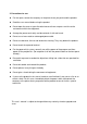
MPEG-4 DVR User’s Manual (Model: 16CH MPEG-4 DVR) This user’s manual is subject to change without any previous notice by function upgrade or addition.
SAFETY PRECAUTIONS CAUTION RISK OF ELECTRIC SHOCK DO NOT OPEN CAUTION: TO REDUCE THE RISK OF ELECTRIC SHOCK, DO NOT REMOVE COVER (OR BACK) NO USER-SERVICEABLE PARTS INSIDE. REFER SERVICING TO QUALIFIED SERVICE PERSONNEL. This label may appear on the rear of the unit due to space limitations.
FCC COMPLIANCE STATEMENT A CLASS A computing device subject to certification by the Commission shall be identified pursuant to Par 2.925 et Seq of the chapter. In addition, the label shall include the following statement: This device complies with Part 15 of FCC Rules. Operation is subject to the following two conditions: (1)This device may not cause harmful interference, and (2)This device must accept any interference received, including interference that may cause undesired operation.
Before Starting Your DVR Operation This document is a basic manual for the DVR users. This manual describes the appearance and name of products, how to configure the system program, and how to use the system. Before using DVR, a user should read the contents of user manual, and then deal with the product considering the precautions defined in the manual.
2. Precautions for use z For the repair, contact the company or the place where you purchased the product. z Read the user manual before using the product. z Do not open the cover at your discretion because there are parts sensitive to the environment within the equipment. z Arrange the power cord safely and do not touch it with wet hands. z Do not use a loose outlet or a damaged power cable. z Do not use benzene, thinner and alcohol for cleaning. They may deform the product.
Table of Contents I. Introduction 1. Package Contents ------------------------------------------ P 2 2. Features ---------------------------------------------------------- P 3 3. Front Panel and Rear Panel Connection -------------- P 4 II. Installation 1. Front Panel ------------------------------------------------------ P 5 2. Rear Panel ----------------------------------------------------- P 9 3. Remote Controller ------------------------------------------ P11 4.
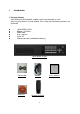
I. Introduction 1. Package Content After purchasing DVR product, unpack it at first and unload it on a flat floor or a place where it is to be located. Then, verify that the following contents are contained. z z z z z z 16CH MPEG-4 DVR Adapter (12V/5.
2. Features This Embedded Linux Stand-Alone DVR can record 16 channel video and 16ch audio at the same time. It provides playback, live display, back-up and network function while it is in recording mode.
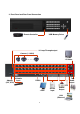
3. Front Panel and Rear Panel Connection Remote Controller USB Memory Driver 16 Loop-Through output Camera (1~16CH) 3 CVBS/ 1 S-Video ••••• Adapter (12V, 6.
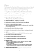
II. INSTALLATION Front Panel 6 1 1. 2 3 4 5 7 CD Tray This can be used for backup media. According to option requirement, DVD also can be mounted. can be used as backup media 2. LED Indicators 1) POWER LED This red LED turns “ON” when Power is “ON”. 2) NETWORK indication LED This green LED will turn “ON”, while data through network is transmitting. 3) COPY LED This green LED will turn “ON” during data COPY through CD-RW or USB Memory driver. 4) REC This red LED will turn “ON” during recording.
POWER NETWORK COPY REC KEY LOCK REMOCON 3. Channel Selection buttons for single channel display Channel selection button from CH1 to CH16 can be used to display given channel on monitor. 4. Function buttons 1) ALT This button is reserved for future use. 2) LOCK In order for only authorized person to operate buttons in front panel, this LOCK button can be utilized. If this button is pressed, all of buttons in front panel are not operated at the same time yellow LOCK LED ON.
4) COPY button (Backup) This COPY button can be used to retrieve some of recorded files into backup media like USB memory drive or CD/ DVR after searching recorded files. According to backup media, Icon (CD or DVD) or (USB memory drive) will be appeared on the left top corner of monitor. 5) (Sequential Display button) If this button is pressed under given video display mode, each video display mode is switched sequentially.
5. Direction button and Enter Button Direction buttons are used to move LEFT, RIGHT, UP and DOWN in menu. They also can be used to input password. ENTER button is used to save parameter, to select parameter in the menu. And also in playback it is used to select one of listed file for playback after searching recorded files by all, time, alarm, motion, manual and so on. 6. Power Button (Power On/ Off button) This Power button can be pressed to turn off DVR power.
Rear Panel 2 1 3 4 5 7 8 9 10 11 6 12 1. Power Input (from Adapter) Connect the adapter to the DVR for DC power supply. (DC 12V/5.8A). 2. 16CH Video Input: 16 channel composite video inputs with BNC connectors Since this DVR automatically detects video format (NTSC or PAL) as soon as power is ON, NTSC or PAL video sources can be connected in DVR. But NTSC and PAL video sources for 16CH video inputs can not be mixed. If they are mixed, DVR can’ not be operated properly. 3.
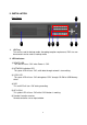
6. 3CH composite Video Output and 1 S-Video Output Two video output (MON1 and MON2) and one S-Video are used to monitor live, playback pictures. They are same video output. The other is used to monitor SPOT output which displays all of connected video channels sequentially. 7. VGA Output VGA output can be connected to LCD monitor or CRT monitor with progressive scan directly which can receive analog R, G, B and synchronization signals. 8. RS232C (It can be utilized for future option.) 9. And 10.
Remote Controller < Remote Controller buttons > < Button Description > No Description Button Name 1 Recording Start/ Stop button REC 1 2 Button LOCK Enable/Disable LOCK 2 3 COPY Start button USB/ CD 3 4 Video CH selection buttons 1,2,3,…,0, +10 (Password Number Input) 5 1) Sequential display button 2) QUAD display button 3) 9 picture display button 4) 16 picture display button Video Picture Display mode 6 If menu button is pressed after this button, audio channel for speaker can be se
Main Menu Display Menu Icons No. ICON NAME No.
16CH MPEG-4 DVR Menu Tree LANGUAGE SEQ DWELL VIDEO FORMAT STOP KEY SPOT DWELL PASSWORD REC SETTING TIME/DATE OSD ADMIN LOCK CAM NO OSD REMOTE CONT ID VIDEO LOSS OSD TIME FORMAT POP-UP DISPLAY DATE FORMAT ADJUST CH DATE/ TIME SET PRIVATE VERSION NO.
III. Main Menu Programming 1. Overview Main Menu Before using your DVR for the first time, you will want to establish the initial settings. This includes setting items such as time and date, password, display, record mode, network and so on. In order to program Main Menu, first press MENU button of front panel in DVR. If ADMIN LOCK is set as YES (factory default is YES), below figure will be appeared.
< MAIN MENU > 2. SYSTEM SETUP To access SYSTEM SETUP, press ENTER button after moving highlight icon to SYSTEM SETUP in MAIN MENU. Below menu will be appeared on monitor. 1) LANGUAGE : Language Selection The language which can be displayed in Menu can be selected. Whenever left or right button is pressed , supported language can be selected. For language selection by graphical user interface, ENTER button can be pressed. Below GUI for language selection will be appeared.
By using up or down button, supported language can be selected. 2) VIDEO FORMAT: NTSC/ PAL Video format is automatically detected after power ON. The detected video information will be displayed on VIDEO FORMAT. User don’t need to change video format. It is recommended that power is “ON” after camera(s) connection for video format recognition. 3) PASSWORD: Move Highlight icon to PASSWORD in the SYSTEM Menu using DOWN or UP button . And press ENTER button to change password.
After inputting old password, input new password using from 0 to 9 button. It needs to input new password again to confirm new password. 4) ADMIN LOCK: YES/ NO Move Highlight icon to ADMIN LOCK in the SYSTEM Menu using DOWN or UP button . If ADMIN LOCK is selected as YES by LEFT or RIGHT, password is requested whenever entering menu. If NO, password isn’t requested.
remote controller, corresponding number button for Remote Cont ID can pressed just after pressing F1 button. If specific DVR with corresponding Remote ID is selected, the ICON for remote controller ID will be disappeared in the DVR. The DVR can be controlled by the remote controller in just live display mode. 6) TIME FORMAT: 24/ 12 HOURS Move Highlight icon to TIME FORMAT in the SYSTEM Menu using DOWN or UP button and press the LEFT or RIGHT button to select 24 HOURS (military time) or 12 HOURS (AM/PM).
It can be moved to DATE or TIME using DOWN or UP button. The movement to year, month, day is done by LEFT or RIGHT button. The year change can be done by DOWN or UP button. Month, day can be adjusted as same way. After setting DATE/ TIME, YES is used in order to save setting value and to return upper menu. NOTE: 1. If you set a date and time that is older than some of your recorded images, it is not easy to manage recorded files. 2. Before starting your DVR, DATE/ TIME should be setting properly.
11) UPGRADE Firmware can be upgraded through USB memory driver or network using Client software. For more detail information, Please see “IV.
NOTE: When all of menu setting are finished, menu mode is escaped, below figure “SAVE?” which ask to save all the setting will be appeared. If all the menu setting is needed to save, “Check Mark” can be pressed. If not, “X” can be selected. 3. DISPLAY SETUP To access DISPLAY SETUP, press ENTER button after moving highlight icon to DISPLAY SETUP in MAIN MENU. Above menu will appear on monitor. 1) SEQ DEWLL TIME: NONE/ 1 to 60 seconds. SEQ DWELL TIME can be adjusted using LEFT or RIGHT button.
2) SPOT DWELL: 1 to 60 seconds. SPOT DWELL TIME can be changed using LEFT or RIGHT button. Or after pressing ENTER button, SEQ DWELL TIME from none, 1 seconds to 60 seconds which decide a period of channel by channel can be selected by UP or DOWN button. And then ENTER button is used for confirming setting value. All of video channels connected with video inputs of DVR can be sequentially switched for SPOT monitoring output.
7) ADJUST CHANNEL: CH1, CH2, CH3, CH4, … , CH16 The camera channel needed to adjust brightness, contrast can be selected by UP or DOWN button. And then next BRIGHT and CONTRST can be adjusted properly. BRIGHTNESS/ CONTRAST : 1 to 99 % BRIGHTNESS can be changed using LEFT or RIGHT button. CONTRAST can be changed using UP or DOWN button. HUE/ SATURATION: 1 to 99 % HUE can be changed using LEFT or RIGHT button. SATURATION can be changed using UP or DOWN button.
8) Private The video channel which don’t want to display on monitor can be selected by LEFT or RIGHT button. Selected channel isn’t displayed on monitor while live or playback display. The private channel is displayed black screen. 9) QUALITY RESET Quality control including brightness, contrast , hue and saturation can be reset by factory initial value by this QUALITY RESET.
4. RECORDING SETUP To access RECORDING SETUP, press ENTER when RECORDING SETUP in MAIN MENU using DOWN or UP and/or LEFT or RIGHT button is highlighted. The menu above will appear on monitor. 1) STOP KEY: DISABLE/ ENABLE In case of manual recording, manual recording is started and stopped by the REC/ STOP button in the front panel of DVR. This REC/ STOP button ENABLE can protect the “recording stop” by unauthorized person intentionally.
2) REC SETTING - Resolution: FULL (4 CIF, D1), HALF(2 CIF, Half D1), NORMAL (CIF) - Quality: VERY LOW, LOW, STANDARD, HIGH, VERY HIGH - FPS: 30 to 1 FPS.(NTSC)/ 25 to 1 FPS (PAL) - REC: MANUAL, Schedule, EVENT, OFF - Audio: ON or OFF - Lock: ON or OFF (If “Lock” is ON, this recorded file isn’t be deleted, even though HDD over-writing is done.
5. EVENT SETUP To access EVENT SETUP, press ENTER when EVENT SETUP in MAIN MENU using DOWN or UP and/or LEFT or RIGHT button is highlighted. The above menu will be appeared on monitor. All the parameters related to EVENT Recording from CH1 to CH16 which include QUALITY, FRAME RATE, DURATION can be selected separately.
1) Event Setup1 parameter Setting - Quality: VERY LOW, LOW, STANDARD, HIGH, VERY HIGH - FPS: 30 to 1 FPS.(NTSC)/ 25 to 1 FPS (PAL) - EVENT: ALARM or MOTION - PRE (Pre-recording): ON/ OFF - Lock: ON or OFF (If “Lock” is ON, this recorded file isn’t be deleted, even though HDD over-writing is done. In order to protect HDD Full, it will be needed to release LOCK function as “OFF” ) It can moved to each items by Movement button, LEFT or RIGHT , UP or DOWN button. Each parameter can be adjusted by ENTER button.
3) MOTION AREA CH and 4) MOTION AREA Motion Area CH selection Motion Area selection The MOVE mode which can just move motion area can move motion area by LEFT or RIGHT or UP or DOWN button. Whenever ENTER button is pressed, marking within above red circle will changed from “DIRECTION” mark to “+” and “-” mark. In the “Direction” mark, motion area can be moved with direction button like LEFT or RIGHT or UP or DOWN button. In the “+” mark, motion area can be enabled by direction button.
6. SCHEDULE SCHEDULE SETUP in the main menu can be selected by movement button such as LEFT , RIGHT or UP , DOWN button. If SCHEDULE is selected by ENTER button, below “Schedule SETUP” figure will be appeared. “OFF” or “Weekly SET” or “ Daily SET” can be configured in Schedule SETUP. It can be selected by UP or DOWN and ENTER button. “OFF” means that there is no Schedule SETUP. It means that there is no recording except manual recording, event recording.
When recording schedule of Weekly SET is finished, or mark in date Box will be added. This mark indicates there is MANUAL setting in specific day. This mark indicates there is EVENT setting in specific day. < Daily SET > If “Daily SET” is selected, below figure will be appeared. If ENTER button is pressed after moving given day in above “Daily SET” figure by movement button such as LEFT , RIGHT or UP , DOWN , below figure will be appeared.
< The buttons of remote controller related to Schedule setup > Schedule Recording reservation 2 Recording time setup. (Left to Right direction) 3 Recording time setup. (Right to Left direction) Schedule Recording Removal 4 Recording time removal. (Left to Right direction) 5 Recording time removal. (Right to Left direction) Direction button 1 2 3 4 5 LEFT Left. RIGHT Right. UP Up. DOWN Down. ENTER Recording Mode changing from ALARM, MOTION to MANUAL.
7. NETWORK SETUP NETWORK SETUP in the main menu can be selected by movement button such as LEFT , RIGHT or UP , DOWN button. If NETWORK is selected by ENTER button, above “NETWORK SETUP” figure will be appeared. 1) CONNECT: STATIC or DHCP STATIC IP or DHCP of CONNECT can be selected by LEFT or RIGHT button. Or after pressing ENTER button, STATIC or DHCP can be selected by UP or DOWN button. And then ENTER button is used for confirming setting value.
For assigning the number of IP address, SUBNET, Gateway and DNS in STATIC IP mode, ENTER button can be pressed on the column of IP address, SUBNET, Gateway and DNS. Then below new NETWORK SETUP figure will be appeared as below figure. The 4 number group with 3 digit expressing IP address, SUBNET, Gateway and DNS can be increased by UP button or decreased by DOWN button. The position movement between 4 numbers can be done by LEFT or RIGHT button.
8) NTP TIME SYNC: OFF/ON DVR can synchronize “standard time” with Time Server using Network Time Protocol. NOTE: If DNS server is not set properly in fixed IP address, this function will not be operated. 9) DDNS STATUS: Dynamic DNS status display (This DDNS status is just readable.) It is recommended not to use this DDNS service for fixed IP or IP sharing machine. NONE – It indicate that DDNS is not used.
8. COPY (BACKUP) BACKUP in the main menu can be selected by movement button such as LEFT , RIGHT or UP , DOWN button. If BACKUP is selected by ENTER button, below “BACKUP” figure will be appeared. 1) DEVICE: USB or CD-R,R/W or DVD R/W USB: USB Memory Driver CD-R,R/W or DVD R/W 2) BACKUP LOG: NONE or ENTER All of log information including DVR power ON/ OFF, recording time, event time and so on can be BACKUP through USB Memory drive.
3) CD/DVD RW FORMAT It is used for CD/DVD RW FORMAT. When recorded files in DVR is copied or backup into CD R/W or DVD R/W, it is recommended to format CD R/W or DVD R/W using this CD/ DVD RW FORMT function before backup. 4) BACKUP INFO: First, connect USB memory drive in USB port of DVR front panel. And then enter menu mode. You can see the information of USB Memory Drive inserted in DVR like USB memory drive manufacturer, total memory size, available memory size.
< The BACKUP procedure using USB memory driver, CD or DVD > 1) In order to search the file which is copied in USB memory or CD or DVR, search button of front panel of DVR can be pressed. Below GUI will be appeared. 2) When Option “ALL” is highlighted, you can select one of recording type including all, manual alarm, motion and schedule recording using UP or DOWN button. According to selection of recording type, recorded files will be listed in below calendar.
3) After selecting the file which want to copy using direction button including LEFT or RIGHT, COPY (BACKUP) button of front panel of DVR can be pressed. In the Below GUI, COPY (BACKUP) time can be decided. 4) If COPY(BACKUP) time is decided by ENTER button, Below GUI will be appeared. The channel(s) which want to copy can be selected here.
< The procedure of backup file playback using simple File Player program > A) Simple File Player is found in backup media like USB memory drive, CD or DVD with backup files. And File Player can be executed for backup files playback. B) Search backup files using “File Open” icon 2 of File Player program. C) Playback the backup file as double-clicking the file.
< Icon Description > No. Name 1 Folder Open This “Folder Open” selection is for playback all the recorded files in same folder. If “Folder Open” icon is clicked, default directory, C:\DVR\BACKUP will be shown. The directory related to backup media like USB or CD can be searched in there. For example, DVR or CD R/W drive is E:\. For file playback, searched folder (the folder which include recorded file to playback) can be selected. And then click play button of No.8. to playback it.
No. Name 7 Power It is used to close File Player Program. 8 Playback Icons Playback : This icon is used for starting playback. STILL/ PAUSE STOP This icon is used for still or pause playback file. This icon is used for stopping playback. GOP SKIP (Backward) This icon is used for faster playback in backward. It is a little faster than normal playback speed. FRAME SKIP (Backward) FRAME SKIP (Forward) GOP SKIP (Forward) This icon is used for faster playback in forward.
No. Name 9 Fast Playback The higher number means, the faster playback. “+” means forward faster playback. “-” means backward faster playback. 10 Capture It is used for capturing single picture or printing it as below figure. Captured single picture is saved into JPEG file. No. Name 11 File Conversion ( from MPEG4 to AVI) THE MPEG-4 file format recorded in HDD can be converted into AVI file format which can be playback using common software like Windows media player installed in most of PC.
If MPEG-4 to AVI file conversion is clicked, left figure will be appeared. First, select file path including MPEG-4 file which is needed to convert into AVI file. If file path is assigned, AVI output path will be assigned in same directory. Second, click “ Convert Raw MP4 to AVI” for conversion. When MPEG-4 to AVI file conversion is finished, left figure will be appeared. Then please just click “OK”.
9. HDD INFORMATION HDD in the main menu can be selected by movement button such as LEFT , RIGHT or UP , DOWN button. If HDD is selected by ENTER button, above “HDD INFORMATION” figure will be appeared. 1) OVERWRITE: HDD OVERWRITE can be used for repetitive recording in to same HDD space. First recorded area in HDD can be replaced with new recording data. OVERWRITE can be selected by LEFT or RIGHT button. Or after pressing ENTER button, OFF or ON can be selected by UP or DOWN button.
If “YES” is selected, below figure will be appeared. If HDD format is finished after 10- 20 seconds, below figure will be appeared. Finally, if OK is selected, everything related to HDD format will be done. 3) INFO: It shows total HDD capacity mounted in DVR.
10. CAMERA SETTING CAMERA in the main menu can be selected by movement button such as LEFT , RIGHT or UP , DOWN button. If CAMERA is selected by ENTER button, above “CAMERA SETTING” figure will be appeared. The movement from CAMERA NO to PTZ type in CAMERA SETTING can be done by UP or DOWN button. 1) CAMERA NO: CH01 – CH16 Camera ID and PTZ protocol for 16 cameras can be separately adjusted in CAMERA SETTING menu. After selecting CAMERA NO. first, camera ID and PTZ can be adjusted.
2) CAMERA ID After selecting CAMERA NO first for CAMERA ID changing, CAMERA ID can be changed by imaginary keyboard of below figure. When ENTER button is pressed, below figure will be appeared. Movement in imaginary keyboard can be done by movement button such as LEFT , RIGHT or UP , DOWN button. If ENTER button is pressed under “SPACE” selection, under-bar character will be generated. If ENTER button is pressed under “BACK” selection, one character which is added last will be eliminated.
4) PTZ ID: ID No. from 00 to 19. PTZ camera ID can be selected for different channel connection. 5) BAUD RATE: Baud rate from 2400 to 19200 BPS can be selected according to PTZ camera.
11. Searching and Playback If search button is pressed for playback, all the search list with on calendar style as below figure will be appeared. The search category such as ALL/ SCHEDULE/ MOTION/ ALARM/ MANUAL and TIME to find out recorded file much faster which want to play can be selected by DOWN or UP button in 1 position. After moving to 2 position using LEFT or RIGHT button, searching day in calendar can be selected by DOWN or UP button. The selected recorded file can be displayed in 3 .
While your DVR is in playback mode, the display channel which want to watch could be selected by display selection button or single channel button. Fast forward (FF, ▶ ▶) or fast backward playback (REW ◀◀) can be done by FF (▶▶) and REW (◀◀) button. In order to freeze picture in playback, PLAY/PAUSE button is used. The movement of single field in still picture mode can be fulfilled by LEFT or RIGHT button. And Jog and shuttle dial also enable user to use FF, REW as well as single frame movement easily.
< The buttons of remote controller related to playback > Display channel selection 1 Full picture display selection 2 QUAD picture display selection When this button is pressed first time, QUAD from ch1 to ch4 will be displayed. Whenever this button is pressed, next QUAD will be displayed sequentially from “ch5-ch8”, “ch9ch12” and “ch13-ch16”. 2 9 picture display selection When this button is pressed first time, 9 picture from ch1 to ch9 will be displayed.
12. Live DISPLAY Mode There are some of live display modes such as single (as full), QUAD, 9 picture, 16 picture and sequential mode regardless recording mode. When there are motion detection or alarm triggering, the video channel which motion is detected or alarm is triggered would be display on monitor during sequential time in DISPLAY menu. 12-1. Live Picture Display Mode A) Full Picture If each video channel is selected, the selected channel will be displayed as full screen.
F) Live audio selection for speaker output: One of audio channels which want to output through speaker can be selected by “MENU” button just after pressing “F1” button. Audio channel can be easily selected by movement buttons in the figure. 12-2.
13. RECORDING This DVR has the performance which can record real-time 16ch video and 16 audio at the same time. Recording enable/ disable, resolution, recording quality, frame rate and audio ON/ OFF, pre-recording ON/ OFF and so on related to individual video channel and audio channel can be adjusted separately. There are several recording modes such as Manual, Event, Schedule. According to recording mode, recording parameter can also be configures separately in RECORDING, EVENT and SCHEDULE menu.
14. PTZ Control Procedure a) Select the camera (which PTZ camera is connected) to control PTZ using Channel Selection button from CH1 to CH16 in front panel of DVR. b) Press PTZ button to select PTZ mode. PTZ MODE OSD upper right corner of monitor. will be displayed on c) Use UP, DOWN button for up and down movement of PTZ camera, LEFT, RIGHT for left and right movement and , buttons for zoom IN and OUT. d) To escape PTZ control mode, press ENTER button or any button.
IV. Software Upgrade Procedure 1. S/W Upgrade procedure 1) Copy upgraded firmware file, “dvr535352XX.tgz” into USB Memory Drive in advance. 2) Insert USB Memory Drive into USB port in front panel of DVR. 3) Press MENU button. 4) Input password and then press ENTER button. 5) Select SYSTEM SETUP menu in main menu. 6) Move to UPGRADE of SYSTEM SETUP. Press ENTER button of front panel in your DVR. Below GUI will be appeared. For firmware upgrade, ENTER button can be pressed again.
If there is no USB memory driver for firmware upgrade, below GUI will be appeared. 7) While “Please wait” is appearing, S/W upgrade will be executed. It takes around 10 minutes. After completing S/W upgrade, your DVR will be automatically rebooted.
8) S/W Upgrade Completion !!! S/W upgrade version will be seen on VERSION NO. of SYSTEM SETUP. Upgrade Version No.
APPENDIX 1. 16CH MPEG-4 DVR Specification Description Input Video Specification 16CH, composite Video, BNC 2CH/ 1CH/ 16CH Output S-Video/ VGA Output (Max. 1024x768) Audio Input/Output Display 16CH Input and 2CH Output 4x4 Image (NTSC:704x480, PAL:704x576) Resolution Compression Recording NTSC: 704x480, 704x240, 352x240, PAL:704x576, 704x288, 352x288 active pixels Algorithm MPEG-4 for video, G.
APPENDIX 2. Pin Description of connectors 1. USB Pin Descriptions (Front panel) 2. VGA Pin Descriptions 1 1 Pin NO. Pin NO. 15 5 Pin description Pin description 1 R 1 VCC 2 G 2 D- (TX-) 3 B 3 D+(TX+) 4 No connected 4 GND 5 No connected 5 SHIELD 6 SYNC 7 No connected 15 No connected 3. RS232 Pin Descriptions 1 9 DVR Pin NO. Pin description Slave Unit like PTZ Camera Pin NO.
4. Alarm Input & Outputs Pin Descriptions 1 1 12 < Alarm Input Pin > < Alarm Output Pin > Pin NO. Pin NO.
5. RS485 Pin Descriptions 1 4 DVR Pin NO. Pin description Slave Unit like PTZ Camera Pin NO. Pin description 1 GND - GND 2 RS485 D+ (TX +) - RS485 D+ (RX +) 3 RS485 D- (TX -) - RS485 D- (RX -) 4 GND - GND 6. LAN port (RJ-45) Pin Descriptions 1 8 Pin NO.
Warranty Guide The quality of this product is guaranteed by strict quality control process and tests. If the Product is damaged despite following the instructions provided in the manual, this Warranty will be in effect, provided the product is damaged within 1 year of purchase. Warranty Guide z Check the Product Warranty Sheet to make sure it is still in effect. z Check the problem again and contact your dealer you purchased from.