Fire Detection Control Panel Series BC216 User Manual Part A ©©by byLabor MEP -Strauss Gefahrenmeldetechnik Sicherungsanlagenbau GmbH.Ges.m.b.H.
User Manual Series BC216 / Part A All rights reserved. Under the copyright laws, no part of this manual or of the software may be multiplied, copied, disseminated, transferred by phototechnical means, reproduced, translated, or reduced to any electronic medium or machine-readable form, in whole or in part, without the prior written consent of Labor Strauss Sicherungsanlagenbau Ges.m.b.H., Vienna. The information written in this User Manual has been worked out with the highest care.
User Manual Series BC216 / Part A Contents 1 1.1 1.2 1.2.1 1.2.2 1.3 1.4 1.5 Introduction . . . . . . . . . . . . . . . . . . . . . . . . . . . . . . . . . . . . . . . . . . . . . . . . . . . . . . . . . . . . . . . . . . . . . . . . . . . . 7 Symbols and type fonts . . . . . . . . . . . . . . . . . . . . . . . . . . . . . . . . . . . . . . . . . . . . . . . . . . . . . . . . . . . . . . . . 8 Important hints for the user and the installer . . . . . . . . . . . . . . . . . . . . . . . . . . . . . . . .
User Manual Series BC216 / Part A 4.7.1 4.7.2 4.7.3 4.7.4 4.7.5 4.7.6 4.7.7 4.7.7.1 4.7.7.2 4.7.8 4.7.8.1 4.7.8.2 4.7.9 4.7.10 4.7.11 4.7.12 4.7.12.1 4.7.12.2 Displaying fire alarms - menu point [Alarms] . . . . . . . . . . . . . . . . . . . . . . . . . . . . . . . . . . . . . . . . Displaying activated actuations - menu point [Activated actuations] . . . . . . . . . . . . . . . . . . Displaying technical messages - menu point [Technical messages] . . . . . . . . . . . . . . . . . . .
User Manual Series BC216 / Part A 6.1.1 6.1.2 6.1.3 6.1.4 6.1.5 6.2 6.3 6.4 Testing of the fire detection control panel and the power supply devices . . . . . . . . . . . . . Testing of detectors . . . . . . . . . . . . . . . . . . . . . . . . . . . . . . . . . . . . . . . . . . . . . . . . . . . . . . . . . . . . . . . . . Testing the alarming devices . . . . . . . . . . . . . . . . . . . . . . . . . . . . . . . . . . . . . . . . . . . . . . . . . . . . . . . . Testing the fire control systems . . . .
User Manual Series BC216 / Part A HB216AE.
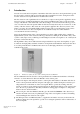
User Manual Series BC216 / Part A 1 Chapter 1 • Introduction 7 Introduction Decades of research and development of LST in the field of fire detection control panel technology and the successful cooperation with renowned international test authorities led to the development of the new fire detection control panels BC216-1 and BCnet216 of LST. The fire detection control panel BC216-1 was drafted as a compact control panel for application in fire detection systems of small and medium size.
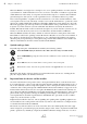
Chapter 1 • Introduction User Manual Series BC216 / Part A This User Manual is not designed as a description of or as an operating instruction for a fire detection system. Therefore, detailed instructions for how to act in case of an alarm or a fault are not given. Individual differences in the variety of components used and in the setup are so extensive that an efficient general description of the system or of the organization in case of an alarm would not be possible.
User Manual Series BC216 / Part A Chapter 1 • Introduction 9 in the expansion of the area surveilled require careful replanning and adaptation of the fire detection system. The fire detection system has to be checked and maintained regularly (at least once a year) by trained and skilled personnel in order to maintain its functions and to avoid false alarms.
Chapter 1 • Introduction User Manual Series BC216 / Part A out the reconditioning. Together with the fire prevention officer you have to determine the additional protective measures that are to be taken until the system is fully operational again. Such measures might include, e.g., special attention by your personnel or fire watches in the area where the fault has occurred.
User Manual Series BC216 / Part A Chapter 1 • Introduction 11 Further approvals are in preparation. 1.4 Warranty Your fire detection control panel Series BC216 has been manufactured with greatest precision and care. Nevertheless, the possibility of malfunctions cannot be excluded entirely. Please contact the authorized installer of your fire detection system in case of a problem.
Chapter 1 • Introduction User Manual Series BC216 / Part A Delay time The delay time consists of reaction- and exploration time. During the reaction period the activation of the transmitting devices for fire alarm messages can be delayed during day-operation of the fire detection system. Exploration time allows the user to find the cause of the alarm and to decide if the fire brigade indeed should be notified.
User Manual Series BC216 / Part A Chapter 1 • Introduction 13 Loop Ring-shaped wiring with bi-directional data-bus to connect intelligent fire detectors (e.g., sensors, detectors) and actuation devices to the fire detection control panel. A wire breakage in the loop leads to a fault display on the control panel but does not affect the functions of the connected devices.
Chapter 1 • Introduction User Manual Series BC216 / Part A ing proper equipment for transmission (e.g., continually monitored telephone cables). The transmitting device for fire alarm messages which can also be operated - additionally to the menu control via the buttons in the field 'TRANSM. DEVICE 1' of the key pad of the control panel is called primary transmitting device.
User Manual Series BC216 / Part A 2 Chapter 2 • Fire detection control panel Series BC216 15 Fire detection control panel Series BC216 The construction of a typical fire detection system, the most important features of the fire detection control panels Series BC216 and the connection of the peripheral components of a fire detection system to the fire detection control panel are described in this chapter. 2.
2.2 Chapter 2 • Fire detection control panel Series BC216 User Manual Series BC216 / Part A Typical construction of a fire detection system with network control panel BCnet216 Basically the network fire detection control panel BCnet216 does not work differently than described from page 15 in Chapter 2.1: "Typical construction of a fire detection system with control panel BC216-1".
User Manual Series BC216 / Part A Chapter 2 • Fire detection control panel Series BC216 17 Basically all fire detectors and other devices that may be connected to a stand-alone control panel of type BC216-1 may also be connected to every single of these BCnet sectional control panels (see from page 15 in Chapter 2.1: "Typical construction of a fire detection system with control panel BC216-1").
Chapter 2 • Fire detection control panel Series BC216 User Manual Series BC216 / Part A In case of an alarm, the user can explore the possible danger prior to the transmission of the fire alarm to the fire brigade by using the alarm delay procedure with deadman´s handle. The standard built-in INFO-bus makes the connection of a fire brigade control unit and of display devices, transmission devices for remote indication units and of other information devices using wiresaving technology possible.
User Manual Series BC216 / Part A Chapter 2 • Fire detection control panel Series BC216 19 for false fire alarms. The fire detection control panel BC216-1, besides automatic adjusting of the sensitivity of the detectors, is capable of displaying a dirt message on the control panel before the detectors activate false alarms due to dirt, by using ADM-, ADMPRO- as well as addressable conventional technology.
Chapter 2 • Fire detection control panel Series BC216 User Manual Series BC216 / Part A played on the control panel. In addition to the zone number, the fire detection control panels Series BC216 are capable of displaying a zone-specific text for every detector zone and a detector-specific text for every single fire detector. Thereby relevant information is provided for the safety personnel fast and without delay.
User Manual Series BC216 / Part A 2.4.4 Chapter 2 • Fire detection control panel Series BC216 21 Actuations Practically any number of actuations can be activated by the fire detection control panels Series BC216. The activation of each actuation is dependent on logic combinations of the alarm activation of detector zones and of single detectors. Actuations can be set for the case of fire ("fire control system"), as well as for faults and technical messages.
3 Chapter 3 • Displaying and operating elements User Manual Series BC216 / Part A Displaying and operating elements The functions and effects of the displaying and operating elements of the fire detection control panel Series BC216 and the optional protocol printer are described in this chapter.
User Manual Series BC216 / Part A Chapter 3 • Displaying and operating elements 23 You operate the fire detection control panel Series BC216 with the clear and sturdy keypad on the front of the case. An illuminated LC-display and light-emitting diodes (LED) are integrated in the keypad as optical display elements. For acoustic alarming, a loud buzzer is fitted in the case of the control panel.
Chapter 3 • Displaying and operating elements User Manual Series BC216 / Part A The third line displays the text information for the element of the current alarm. Is no element text programmed, the second text information for the zone is displayed instead. At installations without elements, the element display is inapplicable. The fourth line displays the last registered alarm (here: the 5th alarm) with zone and element number.
User Manual Series BC216 / Part A 3.6 Chapter 3 • Displaying and operating elements 25 Reset-buttons 'Panel reset'-button: All actual fire alarms, technical messages, fault alarms, faults and actuations are reset in one action on the control panel by pressing this button. With a fire detection control panel BCnet216 this function effects the entire control panel, irrespective of the BCnet sectional control panel on which the button was pressed. For further information see from page 31 in Chapter 4.2.
Chapter 3 • Displaying and operating elements User Manual Series BC216 / Part A The displaying and operating elements of the field TRANSM. DEVICE 1 are reserved for the primary transmitting device, which is exclusively designed for the transmission of fire alarm messages. All further transmitting devices are operated exclusively by the use of the menu and displayed on the LC-display. 'Activated' (red): Is illuminated if the fire alarm has been transmitted to the primary transmitting device (i.e.
User Manual Series BC216 / Part A Chapter 3 • Displaying and operating elements 27 this is only possible by the use of the menu (see from page 43 in Chapter 4.7.10: "Displaying and operating alarming devices - menu point [Alarming device:]"). The displaying and operating elements of the field ALARM. DEVICE 1 are out of function if the supervised siren output of the fire detection control panel has not been parameterized as alarming device. 3.
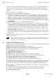
Chapter 3 • Displaying and operating elements 330 21.12.2002 08:45 ENABLEMENT 0002 331 21.12.2002 08:47 AUTHORIZATION EXIT Figure 6: User Manual Series BC216 / Part A 1.Floor User level Storage area Example of a protocol print-out The continuous line number, date, time, event (with zone and element number, if available), event text 1, event text 2 are printed (from left to right). 08:32: The detector 2/14 activated an alarm; due to this the actuation 12 and the alarming device Nr.
User Manual Series BC216 / Part A 4 Chapter 4 • Basic operation of the fire detection control panels Series BC216 29 Basic operation of the fire detection control panels Series BC216 The basic functions of the fire detection control panels Series BC216, together with their operation, are described in this chapter. Almost all necessary operations can be executed by the use of the menu. For a few operations some special buttons are mandated by standards.
Chapter 4 • Basic operation of the fire detection control panels Series BC216 User Manual Series BC216 / Part A By confirming the menu point [Exit authorization?], authorization level 2 is left. Has no operation occurred for 15 minutes, the control panel returns to authorization level 1 automatically. The numeric code for authorization level 2 ("user code") is set by the installer of the fire detection system together with the user.
User Manual Series BC216 / Part A Chapter 4 • Basic operation of the fire detection control panels Series BC216 31 During activities that require authorization level 4, the fire detection control panel is usually completely out of service! 4.2 Operations using single buttons Single buttons are provided on the control panel for the following operations: 4.2.
Chapter 4 • Basic operation of the fire detection control panels Series BC216 User Manual Series BC216 / Part A With the possibility to reactivate the primary alarming device, you can repeat a prematurely interrupted evacuation alarm of a building without activating a new alarm as long as the fire alarm is still displayed on the control panel! After resetting the fire alarm, the repetition of the evacuation alarm is only possible by renewed activation of an alarm.
User Manual Series BC216 / Part A Chapter 4 • Basic operation of the fire detection control panels Series BC216 33 By exception of the primary transmitting device, all other transmitting devices are operated exclusively by the use of the menu. Only the primary transmitting device is equipped with an alarm delay procedure and timer activation. 4.3 Operations using the menu The displaying and operating menus are similar in structure to the menus of modern programs for PCs.
Chapter 4 • Basic operation of the fire detection control panels Series BC216 User Manual Series BC216 / Part A the beginning of a code and leads you straight to the menu point [Authorization code:]. This happens also if you are in a display-menu point such as, e.g., the display of current fire alarms. This menu-quick-operation can not be used while you are viewing the event memory.
User Manual Series BC216 / Part A Chapter 4 • Basic operation of the fire detection control panels Series BC216 Authorization level 1 Main menu points Authorization levels 2 and 3 Submenu points Main menu points Alarms Alarms Activated actuations Activated actuations Technical messages Technical messages Faults Faults Disablements Disablements Test conditions Submenu points Test conditions Zone: *) Disable Enable Activate Test condition on Measured value/ maintenance Actuation: Disable
4.5 Chapter 4 • Basic operation of the fire detection control panels Series BC216 User Manual Series BC216 / Part A Entering and exiting authorization level 2 To enter authorization level 2 from authorization level 1, you have to enter the 4-digit user code programmed by the installer.
User Manual Series BC216 / Part A Chapter 4 • Basic operation of the fire detection control panels Series BC216 37 The number of incorrect inputs is limited. After 5 incorrect inputs, the input of the installer-code is locked for 15 minutes. To return from authorization level 3 to authorization level 1, you have to scroll to the main menu point [Exit authorization?] either by using the menu or by using the menu-quick-operation and confirm the menu point by using the '↵'-button.
4.7.2 Chapter 4 • Basic operation of the fire detection control panels Series BC216 User Manual Series BC216 / Part A Displaying activated actuations - menu point [Activated actuations] Scroll through all activated actuations by using the '↑↓'-buttons (details see from page 55 in Chapter 5.3: "Activation condition of actuations"). Note that activations of transmitting devices and of alarming devices are displayed as activated actuations as well. 1.TR-DEV.ACT 01
User Manual Series BC216 / Part A Chapter 4 • Basic operation of the fire detection control panels Series BC216 39 1.TECH.DIS 0003 Figure 11: Example for the display of the disablement of a technical message, zone 3. In this case, the '↵'-button has a special function: The part of the system whose disablement is currently displayed is enabled by using this button (Menu-quick-operation). 4.7.
Chapter 4 • Basic operation of the fire detection control panels Series BC216 User Manual Series BC216 / Part A No alarm is transmitted by detector zones that are disabled, faulted or put in test condition. A detector zone that is disabled, faulted or put in test condition and is programmed in a two-zone dependency is removed from this dependency.
User Manual Series BC216 / Part A Chapter 4 • Basic operation of the fire detection control panels Series BC216 41 If the function "measured value/maintenance" is selected, the LC-display shows the measured value at the time of function selection of this detector. Also displayed is the time that the detector presumably will work reliably without maintenance at stable environmental conditions. Zone: 0001/016 Meas.val. maint. 125 >>12 Figure 13: Display when selecting the function "Measured val./Maint.
Chapter 4 • Basic operation of the fire detection control panels Series BC216 User Manual Series BC216 / Part A The activation of an actuation for test purposes acts like a real activation! Consider that this may lead to an unintended activation of an extinguishing system and thus to danger to life and to costly damage of property. Contact the responsible person (e.g.
User Manual Series BC216 / Part A Chapter 4 • Basic operation of the fire detection control panels Series BC216 43 If the parameters of the transmitting device have been set to take the device out of operation automatically in authorization level 2 or 3 (see from page 36 in Chapter 4.5: "Entering and exiting authorization level 2" and page 36 in Chapter 4.
Chapter 4 • Basic operation of the fire detection control panels Series BC216 User Manual Series BC216 / Part A The event memory can be accessed by using the menu point [Event memory]. You can set one of the possible filters [Display all], [Control panel] or [Detector zones] for the displaying of the events by the use of the '↑↓'-buttons. After confirming the chosen filter with the '↵'-button, the most recent event is displayed with its running number.
User Manual Series BC216 / Part A Chapter 4 • Basic operation of the fire detection control panels Series BC216 45 4.7.12.4 Correcting the clock time - submenu point [Clock time correction] The built-in quartz clock has an accuracy of a few seconds per year. In case of higher deviations, the time of the clock can be corrected by the maintainer during the periodic maintenance. The user, too, can correct the time displayed on the LC-display in normal condition for up to ±10 minutes.
Chapter 4 • Basic operation of the fire detection control panels Series BC216 User Manual Series BC216 / Part A 4.7.12.9 Displaying the installed componentries - submenu point [Componentries] You can display the corresponding number of the software version and an additional information (such as, e.g., the serial number) of the componentries installed in the control panel by using the buttons '↑↓'. Minimum requirement for this submenu point is authorization level 2. 4.7.12.
User Manual Series BC216 / Part A Chapter 4 • Basic operation of the fire detection control panels Series BC216 47 With a single measured value print-out, the output of current events is suppressed until the print-out has been finished. With the periodical measured value print-out, occurring events are printed instantly, therefore interrupting the running measured value print-out shortly.
4.8 Chapter 4 • Basic operation of the fire detection control panels Series BC216 User Manual Series BC216 / Part A Operating the control panel by using the fire brigade control unit A fire brigade control unit offers the fire brigade the possibility to operate the necessary functions of the control panel uniformly. Fire brigade control units are locally designed differently and sometimes have to fulfill different functions. Thus only the basic operations can be described in this User Manual.
User Manual Series BC216 / Part A 5 Chapter 5 • Operating conditions of fire detection control panels Series BC216 49 Operating conditions of fire detection control panels Series BC216 This chapter describes the operating conditions of a fire detection control panel or -system and the possibilities of operation resulting from these conditions. The following operating conditions are internationally standardized: normal condition (i.e.
Chapter 5 • Operating conditions of fire detection control panels Series BC216 User Manual Series BC216 / Part A By using the '↑↓'-buttons, you can browse in an event-category (e.g., in all current alarms); by using the '← →'-buttons, you can scroll to the previous or the next main menu point. (See from page 34 in Chapter 4.4: "Overview of the display- and operation menus").
User Manual Series BC216 / Part A Chapter 5 • Operating conditions of fire detection control panels Series BC216 51 No rules or instructions beyond those necessary for the operation of the control panel are given in this User Manual. You have to analyze the site-specific dangers and gain the corresponding measures in case of emergency yourself, or you delegate this responsibility to a skilled person.
Chapter 5 • Operating conditions of fire detection control panels Series BC216 User Manual Series BC216 / Part A The activation of a transmitting device and of an alarming device are classified as an actuation and therefore activate the red light-emitting diode 'Actuation activated' as well. If the parameters have been set accordingly, the red light-emitting diodes of all alarming zones, actuations, transmitting devices and alarming devices are illuminated on the optional LED-display field.
User Manual Series BC216 / Part A Chapter 5 • Operating conditions of fire detection control panels Series BC216 53 The information on the transmission to the fire brigade and the sirens given in this chapter are only valid for the common case that the panel was configured during commissioning so that an alarm notification of the fire brigade takes place by the primary transmitting device and the local sirens act as primary alarming device. The operating and displaying devices of the fields TRANSM.
Chapter 5 • Operating conditions of fire detection control panels Series BC216 User Manual Series BC216 / Part A Starting at the display of alarms you can scroll to the main menu points [Faults] and [Disablements] by using the '← →'-buttons. In these menu points you can scroll through the events by using the '↑↓'-buttons. Determine - either by yourself or through other qualified persons - the actual potential for danger in the locations where a fire has been detected.
User Manual Series BC216 / Part A 5.2.5 Chapter 5 • Operating conditions of fire detection control panels Series BC216 55 Fire alarm condition - special case: alarm in an interdependence of two detectors Interdependencies of two detectors can be set during planning for exceptional local circumstances. In this case the condition of fire alarm is attained only if at least two detectors of an interdependence of two detectors are in the state of alarm at the same time.
Chapter 5 • Operating conditions of fire detection control panels Series BC216 User Manual Series BC216 / Part A line will show the second zone text, if this is available. The fourth line is reserved for fire alarm messages. If the parameters have been set accordingly, the light-emitting diodes of all activated actuations are illuminated on the optional LED-display field. Additional information (e.g.
User Manual Series BC216 / Part A Chapter 5 • Operating conditions of fire detection control panels Series BC216 57 The internal buzzer is sounding constantly. You can silence the internal buzzer by using the button 'Silence buzzer'. The buzzer is activated again by each further received technical message and can be reset in the same way. If no event of higher priority is currently on the control panel the menu jumps automatically to the menu point [Technical messages].
Chapter 5 • Operating conditions of fire detection control panels Series BC216 User Manual Series BC216 / Part A display of the panel, the yellow light-emitting diode 'Technical message' and the buzzer are activated by these messages also. Technical messages of that kind are: The processing of a sabotage-message of a key safe. Usually this message is reported to a burglar alarm control panel and indicated there as a burglar alarm- or sabotage message.
User Manual Series BC216 / Part A Chapter 5 • Operating conditions of fire detection control panels Series BC216 59 At a fault in the primary transmitting device or the primary alarming device, the corresponding yellow LED-displays are flashing. At a fault in the power supply, the yellow light-emitting diode 'Energy fault' is flashing. At a fault in the system, the yellow light-emitting diode 'System fault' is flashing or is illuminated, depending on the kind of fault (see from page 9 in Chapter 1.2.
Chapter 5 • Operating conditions of fire detection control panels Series BC216 Condition User Manual Series BC216 / Part A Displaying (1st line) Effect Fault in an element (e.g., Nr. 5) of a detector zone (e.g., Nr. 3) for technical 1.TECH.FLT messages 0003/005 The transmitting of an alarm from the concerning element to the control panel is no longer possible. Fault in a detector zone (e.g., Nr. 5) for fault messages1) 1.FLT.FLT 0005 1.FLT.FLT 0005/014 1.ACTU.FLT 0002 1.ACTU.
User Manual Series BC216 / Part A 81* =8/$66 Chapter 5 • Operating conditions of fire detection control panels Series BC216 61 The fire detection system is supplied with power by the stand-by battery in case of a fault with mains power shut down. The required bridging time is regulated by local guidelines. Often, a bridging time of 72 hours is demanded.
Chapter 5 • Operating conditions of fire detection control panels Series BC216 User Manual Series BC216 / Part A At disablement of the primary transmitting device or the primary alarming device, the corresponding yellow disablement-LED-displays are illuminated. The menu jumps automatically to the menu point [Disablements] 30 seconds after any button was pressed last, if no event of higher priority is currently on the control panel. The first line of the LC-display shows the first disablement.
User Manual Series BC216 / Part A Chapter 5 • Operating conditions of fire detection control panels Series BC216 63 In case of several current disablements, you can tell the order of their occurrence by the number in front of the disablement message. Starting with the tenth disablement, a "+" is written instead of the number. If all elements of a zone have been disabled individually, the whole detector zone is rated as disabled.
Chapter 5 • Operating conditions of fire detection control panels Series BC216 User Manual Series BC216 / Part A Additional information (e.g., date and time of the test procedure, the number of current test procedures, hints for operating the menu, hints for authorization) can be displayed by using the 'Info'-button. You can scroll through all current test procedures by using the '↑↓'-buttons.
User Manual Series BC216 / Part A 6 Chapter 6 • Ensuring the efficacy of the system by the user 65 Ensuring the efficacy of the system by the user In order to ensure the efficacy of the fire detection system the user periodically should make sure that the system fulfills its determined purposes in all areas and that it functions fully and well. 81* =8/$66 6.1 This internal control may also be ordered by the regulatory agencies.
Chapter 6 • Ensuring the efficacy of the system by the user User Manual Series BC216 / Part A After finishing the testing of the detectors you have to terminate the test condition immediately. Detection zones in test condition cannot transmit an alarm to the fire brigade, the alarming devices and the actuations in case of fire! Therefore put detector zones in test condition only for test purposes and terminate this condition as soon as possible. 6.1.
User Manual Series BC216 / Part A 6.3 Chapter 6 • Ensuring the efficacy of the system by the user 67 Reconditioning and maintenance Parts of the system that have a fault are not able to perform their functions efficiently or at all. Therefore have faults repaired as soon as possible by a qualified and authorized company, preferably the one that performs the periodic maintenance of your system.
7 Chapter 7 • Event memory - entries User Manual Series BC216 / Part A Event memory - entries You can browse in the event memory by the use of the '↑↓'-buttons. The first three lines of the LCdisplay show the event text as well as the free programmable text information on the event, and provide additional information on events on the control panel. By pressing the 'Info'-button, additional texts (e.g.
User Manual Series BC216 / Part A Chapter 7 • Event memory - entries Event Event text Text 2nd line Text 3rd line Test condition off FLT.TEST.T 0001/001 zone text 1 zo. text 2 / element text Test condition on FLT.TEST 0001/001 zone text 1 zo. text 2 / element text Additional text (info-button) Actuations, Actuation elements Activation ACTU.ACT 0001/001 actuation text 1 actu.text2 / element text Activation termination ACTU.ACT.T 0001/001 actuation text 1 actu.
Chapter 7 • Event memory - entries Event Test activation termination User Manual Series BC216 / Part A Event text AL-DEV.TEST.T Text 2nd line 01 Text 3rd line alarming device text 1 alarming device text 2 user level Additional text (info-button) Control panel events Activation term. exing. sys. EXTING.ACT.T Activation exing. system EXTING.
User Manual Series BC216 / Part A Chapter 7 • Event memory - entries Event Fault termination function module 2 Event text Text 2nd line FAULT.T Text 3rd line 71 Additional text (info-button) FM2 fault cause LAB fault cause Fault termination INFO-bus SER-IF.FLT.T 0/01 Fault termination LAB48 FAULT.T Fault termination loop LOOP.FLT.E Fault termination power unit ENERGY FAULT.T power unit Notification new year CLOCK TIME SHIFT Happy New Year! Sabotage fire brig.
8 Chapter 8 • Index User Manual Series BC216 / Part A Index Activation condition of actuations, 55 Actuation, 21 - Display, 38, 41 - Light-emitting diode, 25 - Operate, 41 - Two-zone dependency, 56 Alarm counter, 44 Alarm delay, 18 - Alarm delay procedure, 11, 32 - Button, 26 - Day/night-operation, 32 - Day / night operation, 26 - Delay time, 12 - Exploration time, 32, 53 - Reaction time, 32, 53 Alarm verification, 11 Alarming device, 15, 20, 26 - Display, 43 - Number, 20 - Operate, 43 - Primary, 1
User Manual Series BC216 / Part A Chapter 8 • Index Software version, 8, 46 Specifications, 67 Stand-by battery, 18, 65 - Disposal, 65 Standards, 10 System fault, 10, 25 Technical message, 49, 56 - Display, 38 - Light-emitting diode, 25 - Reset, 57 - Self holding, 57 - Self resetting, 57 Test condition, 63, 65 - Display, 39 - Light-emitting diode, 25 Timer, 18, 26, 32 Transmitting device, 13, 17 - Day/night operation, 32 - Display, 42 - For fault messages, 25 - For fire alarm, 13, 25 - Number, 20 - Ope