
Logic Host Adapters USER'S GUIDE Ultra320 SCSI


Installing Your Ultra320 SCSI Host Adapter 2-3
Version 2.2 Copyright © 2002–2004 by LSI Logic Corporation. All rights reserved.
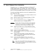
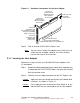
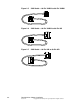
Figure 2.1 Hardware Connections for the Host Adapter
Step 5. Find an unused PCI/PCI-X/PCI Express slot.
Note: You can insert a 64-bit host adapter into a 32-bit slot if no
64-bit slots are available. However, this limits the data
transmission rate to 32-bit transfers.
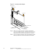
2.1.2 Inserting the Host Adapter
Follow these steps to install your Ultra320 SCSI host adapter in the
PC mainboard.
Step 1. Remove the blank bracket panel on the back of the computer that
is aligned with the PCI/PCI-X/PCI Express slot you have selected.
Save the bracket screw.
Step 2. Carefully insert the edge connector into the PCI Express slot.
Caution: Apply even pressure to both top corners of the board while
inserting it, as shown in Figure 2.2.
Caution: Do not apply pressure to the center of the board, or to any
add-on cards that are connected to the host bus adapter.
Channel A
68-Pin Internal
High Density (HD)
SCSI Interface
Channel B
68-Pin Internal
HD SCSI Interface
68-Pin External
Very High Density Cable
Channel A & B
Busy LED
J5 Connector
Channel B
68-Pin External
Channel A
J4 Connector
J6 Connector
J1 Card Connector
Universal Type Board Edge
PCI/PCI-X/PCI Express Bus to Mainboard
SCSI J3 Connector
Interconnect (VHDCI)
VHDCI SCSI
J2 Connector