
User`s guide

LSI Confidential
3-18 Host Bus Adapter Characteristics
Copyright © 2006-2007 by LSI Corporation. All rights reserved.
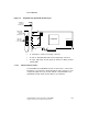
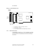
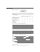
3.1.9 SAS31601E HBA Characteristics
The SAS31601E uses a standard PCI bracket. Figure 3.9 shows the
HBA and its bracket.
3.1.9.1 LEDs
The SAS31601E HBA has sixteen LEDs, labeled A0–A15, that turn
green to indicate an activity condition on any of the sixteen PHYs. There
are sixteen LEDs, labeled LNP0–LNP15, that turn yellow to indicate a
link not present condition on any of the sixteen PHYs. See Figure 3.9 for
LED locations.
The SAS31601E HBA has one LED for each of the two LSISAS1068E
chips. It flashes green to indicate the LSISAS1068E heartbeat. The
Activity LED turns green to indicate activity on any PHY.
3.1.9.2 Connectors
This section describes the connectors on the SAS31601E HBA. See
Figure 3.9 for connector locations.
PCI Express Connector (J1) – The PCI Express interface has eight
PCI Express lanes, which provide possible host-side maximum
transmission and reception rates of up to 4.0-GB/s. The SAS31601E
supports x8, x4, and x1 PCI Express link widths, and automatically
downshifts if plugged into either a x4 connector or into a x8 connector
that is wired as a x4 connector. The connection is made through the
edge connector J1. The signal definitions and pin numbers conform to
the PCI Express specifications.
Activity LED Connector (J2) – The connector is a 4-pin, right angle,
0.1-inch pitch, pin header for driving external activity LEDs.
SAS/SATA Connectors (J4, J5, J6 and J7) – The SAS31601E
supports SAS connections through connectors J4, J5, J6 and J7. These
connectors are SFF-8088 mini-SAS external right-angle connectors.