USER’S GUIDE MegaRAID® 6Gb/s SAS RAID Controllers November 2009 41450-02 Rev.
This document contains proprietary information of LSI Corporation. The information contained herein is not to be used by or disclosed to third parties without the express written permission of an officer of LSI Corporation. LSI products are not intended for use in life-support appliances, devices, or systems. Use of any LSI product in such applications without written consent of the appropriate LSI officer is prohibited.
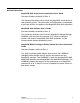
Preface This document is the primary reference and user’s guide for the LSI MegaRAID® Serial Attached SCSI/SATA II RAID controllers based on the 6Gb/s SAS/SATA RAID On-a-Chip devices. This document contains complete installation instructions for these RAID controllers and includes specifications for them. The MegaRAID 6Gb/s Serial Attached SCSI (SAS) RAID controller family consists of the following controllers: • MegaRAID SAS 9240-4i PCI Express 2.
• MegaRAID SAS 9280-8e PCI Express 2.0 Low-Profile SerialAttached SCSI/SATA II Disk Array Controller with External Connectors • MegaRAID SAS 9280DE-8e PCI Express 2.0 Low-Profile Serial-Attached SCSI/SATA II Disk Array Controller with External Connectors For information about how to configure the RAID controllers, refer to the MegaRAID SAS Software User’s Guide. For information about the operating system drivers, refer to the MegaRAID SAS Device Driver Installation User’s Guide.
Related Publications MegaRAID SAS Device Driver Installation User’s Guide Document Number: 80-00163-01 Rev. D This document describes how to install the MegaRAID device driver for your operating system. The information in this document is independent of the back-end bus and applies to the MegaRAID SAS RAID controllers. MegaRAID SAS Software User’s Guide Document Number: 80-00156-01 Rev.
Conventions The following table describes how the user interacts with the product. Notation Example Meaning and Use Courier typeface .nwk file Names of commands, files, and directories, as well as code and screen messages, are shown in Courier. Bold typeface fd1sp In a command line, keywords are shown in bold, non-italic typeface. Enter them exactly as shown. Italics module In command lines and names, italics indicate user variables. Replace italicized text with appropriate userspecified items.
Safety Instructions Use the following safety guidelines to help protect your computer system from potential damage and to ensure your own personal safety. Note: Use the MegaRAID 6Gb/s SAS RAID controllers with UL-listed Information Technology Equipment (ITE) products only.
• Make sure that equipment does not rest on your computer system cables and that the cables are not located where they can be stepped on or tripped over. • Do not spill food or liquids on your computer. If the computer gets wet, consult the documentation that came with it. • Do not push any objects into the openings of your computer. Doing so can cause fire or electric shock by shorting out interior components. • Keep your computer away from radiators and heat sources.
Protecting Against Electrostatic Discharge – Static electricity can harm delicate components inside your computer. To prevent static damage, discharge static electricity from your body before you touch any of your computer’s electronic components, such as the microprocessor. To discharge static electricity, touch an unpainted metal surface, such as the metal around the card-slot openings at the back of the computer.
x Preface Copyright © 2009 by LSI Corporation. All rights reserved.
Contents Chapter 1 Overview 1.1 1.2 1.3 1.4 1.5 1.6 1.7 1.8 Overview SAS Controller Descriptions General Description Configuration Scenarios Benefits of the SAS Interface 1.5.1 PCI Express Architecture 1.5.2 Operating System Support Summary of SAS RAID Controller Characteristics 1.6.1 SAS Features 1.6.2 SAS Array Limitations 1.6.3 SATA II Features 1.6.4 PCI Express Performance 1.6.5 Usability Features 1.6.6 Flexibility Features 1.6.7 Drive Roaming 1.6.
2.5.2 Connectors to Drives 2-9 Connecting the SAS RAID Controller with External Connectors to a Drive Enclosure 2-10 Chapter 3 MegaRAID SAS RAID Controller Characteristics 3.1 MegaRAID 6Gb/s SAS RAID Controller Family 3.1.1 MegaRAID SAS 9240 RAID Controllers 3.1.2 MegaRAID SAS 9260 RAID Controllers 3.1.3 MegaRAID SAS 9261 RAID Controller 3.1.4 MegaRAID SAS 9280 RAID Controllers 3.2 MegaRAID SAS 6Gb/s RAID Controller Characteristics 3.3 Technical Specifications 3.3.1 RAID Controller Specifications 3.3.
Customer Feedback Contents Copyright © 2009 by LSI Corporation. All rights reserved.
xiv Contents Copyright © 2009 by LSI Corporation. All rights reserved.
Figures 1.1 1.2 2.1 2.2 2.3 2.4 2.5 2.6 3.1 3.2 3.3 3.4 3.
xvi Contents Copyright © 2009 by LSI Corporation. All rights reserved.
Tables 1.1 1.2 3.1 3.2 3.3 3.4 3.5 3.6 3.7 3.8 3.9 3.10 3.11 3.12 3.
xviii Contents Copyright © 2009 by LSI Corporation. All rights reserved.
Chapter 1 Overview This chapter provides an overview of the MegaRAID 6Gb/s Serial Attached SCSI/Serial ATA II controllers with RAID control capability. It consists of the following sections: 1.1 • Section 1.1, “Overview” • Section 1.2, “SAS Controller Descriptions” • Section 1.3, “General Description” • Section 1.4, “Configuration Scenarios” • Section 1.5, “Benefits of the SAS Interface” • Section 1.6, “Summary of SAS RAID Controller Characteristics” • Section 1.
two similar technologies on the same controller, within the same enclosure, and in the same virtual drive. Note: LSI recommends that you carefully assess any decision to mix SAS drives and SATA drives within the same virtual drives. Although you can mix drives, LSI strongly discourages the practice. LSI offers a family of MegaRAID SAS RAID controllers addressing the needs for both internal and external solutions.
The SAS controllers support the ANSI Serial Attached SCSI standard, version 2.0. In addition, the controller supports the SATA II protocol defined by the Serial ATA specification, version 1.0a. Supporting both the SAS interface and the SATA II interface, the SAS controller is a versatile controller that provides the backbone of both server and high-end workstation environments. Each port on the SAS RAID controller supports SAS devices, SATA II devices, or both, using the following protocols: 1.
1.3 • The MegaRAID 6Gb/s SAS 9260-8i PCI Express 2.0 Low-Profile Serial-Attached SCSI/SATA II Disk Array Controller controls eight internal SAS/SATA ports through two SFF-8087 x4 internal mini SAS connectors. • The MegaRAID 6Gb/s SAS 9260DE-8i PCI Express 2.0 Low-Profile Serial-Attached SCSI/SATA II Disk Array Controller controls eight internal SAS/SATA ports through two SFF-8087 x4 internal mini SAS connectors and offers data security using disk encryption.
These SAS controllers are based on the LSISAS2108 RAID On-a-Chip (ROC) device or the LSISAS2008 PCI Express-SAS/SATA I/O Processor chip. These devices are compliant with the Fusion-MPT™ architecture and provides a PCI Express x8 interface. Note: All of these RAID controllers provide an x8 PCI Express 2.0 interface. The LSISAS2108 ROC device provides an eight-lane, 5-Gb/s PCI Express host interface, eight 6.0 Gb/s SAS ports or eight 3.
• 3Gb/s SATA II • Staggered spin-up • Hot plug • Native command queuing • Activity and fault indicators for each PHY • Port selector (for dual-port drives) Each port on the SAS controllers supports SAS devices, SATA II devices, or both using SSP, SMP, STP, and SATA II. SSP enables communication with other SAS devices. SATA II enables the SAS controllers to communicate with other SATA II devices. 1.
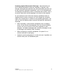
(PSBRAM), nonvolatile static random access memory (NVSRAM), and Flash ROM. Figure 1.1 Example of an LSI SAS Direct-Connect Application SAS/SATA II Device SAS/SATA II Device SAS PCI Express RAID Controller SAS/SATA II Device 32-Bit Memory Address/Data Bus I2 C Interface Flash ROM/ PSBRAM/ NVSRAM I2 C SAS/SATA II Device PCI Express Interface Figure 1.2 shows an example of a SAS RAID controller configured with an LSISASx12 expander that is connected to SAS drives, SATA II drives, or both. Figure 1.
1.5 Benefits of the SAS Interface SAS is a serial, point-to-point, enterprise-level device interface that leverages the proven SCSI protocol set. SAS is a convergence of the advantages of SATA II, SCSI, and Fibre Channel, and is the future mainstay of the enterprise and high-end workstation storage markets. SAS offers a higher bandwidth per pin than parallel SCSI, and it improves signal and data integrity.
1.5.2 Operating System Support The MegaRAID 6Gb/s SAS RAID controllers supports the following operating systems: • Windows Vista, Server 2003, and Windows Server 2008 • Red Hat Linux • SUSE Linux • Novell NetWare • SCO OpenServer • SCO UnixWare • Solaris • FreeBSD To download the latest operating system drivers, go to: http://www.lsi.com/cm/DownloadSearch.do.
1.6.
• Supports STP to enable communication with a SATA II device through an attached expander • Provides a serial, point-to-point, enterprise-level storage interface • Simplifies cabling between devices • Provides a scalable interface that supports up to 240 devices through the use of expanders Note: 1.6.2 The number of devices varies depending on the MegaRAID product. Check the LSI web site (http://www.lsi.com) for specific details about your product.
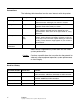
SAS 9240-8i SAS 9260-4i SAS 9260-8i SAS 9261-8i SAS 9280 4i/4e SAS 9280-8e SAS RAID Controller Array Limitations SAS 9240-4i Table 1.1 Maximum drives per controller 16* 16* 32 32 32 240 240 Maximum hot spares per controller 8 8 32 32 32 240 240 Maximum spans per virtual drive 8 8 8 8 8 8 8 Maximum enclosures per port** 2 2 2 2 2 10 10 Number of ports 1 2 1 2 2 2 2 Specification * - Can support up to 64 devices, but only 16 can be used in a RAID configuration.
1.6.3 SATA II Features The following list describes the SATA II features of the RAID controllers: 1.6.
• Provides one LED signal for each PHY to indicate link activity (this is a fault LED only for controllers with internal port connectors) Note: 1.6.6 The SAS 9280-8e RAID controller and the SAS 9280DE-8e RAID controller do not have any LEDs to indicate link activity. • Provides an I2C interface for enclosure management • Supports the internal SAS Sideband signal SFF-8485 (SGPIO) interface Flexibility Features These features increase the flexibility of the RAID controllers: 1.6.
Follow these steps to use drive roaming: Step 1. Turn off power to the server and all drives, enclosures, and system components. Disconnect the power cords from the system. Step 2. Open the host system by following the instructions in the host system technical documentation. Step 3. Move the drives to different positions on the backplane to change the targets. Step 4. Determine the SAS target requirements. Step 5. Perform a safety check. a. Make sure that the drives are inserted correctly. b.
Note: When you migrate drives, move only the drives that make up the virtual drive (not all of the drives in an array), so you do not see an NVRAM mismatch error (providing a configuration is on the destination controller). The NVRAM mismatch error appears only if you move all of the drives to the other controller. Step 2. Turn off power to the server and all drives, enclosures, and system components. Disconnect the power cords from the systems. Step 3.
1.7 Hardware Specifications You can install the MegaRAID 6Gb/s SAS RAID controllers in a computer with a motherboard that has a PCI Express slot. Table 1.2 describes the hardware configuration features for the MegaRAID 6Gb/s SAS RAID controllers. Table 1.
Table 1.2 MegaRAID 6Gb/s SAS RAID Controller Features (Cont.
1.8 Technical Support For assistance installing, configuring, or running your MegaRAID 6Gb/s SAS RAID controller, contact LSI Technical Support. Click the following link to access the LSI Technical Support page for storage and board support: http://www.lsi.com/support/storage/tech_support/index.html From this page, you can send an email or call Technical Support, or submit a new service request and view its status.
1-20 Overview Copyright © 2009 by LSI Corporation. All rights reserved.
Chapter 2 MegaRAID SAS Hardware Installation This chapter describes the procedures you can follow to install the MegaRAID 6Gb/s Serial Attached SCSI/Serial ATA II controllers with internal and external connectors. It consists of the following sections: 2.1 • Section 2.1, “Requirements” • Section 2.2, “Quick Installation” • Section 2.3, “Detailed Installation” • Section 2.4, “After Installing the RAID Controller” • Section 2.
2.2 Quick Installation The following steps are for quick installation of your MegaRAID 6Gb/s SAS RAID controller. These steps are for experienced computer users or installers. Section 2.3, “Detailed Installation,” contains the steps for all others to follow. Step 1. Turn off the power to the system, all drives, enclosures, and system components, and disconnect the PC power cord. Step 2. Open the cabinet of the host system by following the instructions in the host system technical documentation. Step 3.
2.3 Detailed Installation This section provides detailed instructions for installing your MegaRAID 6Gb/s SAS RAID controller. Step 1. Unpack the MegaRAID 6Gb/s SAS RAID controller Unpack and remove your RAID controller. Inspect it for damage. If it appears damaged, or if any of the following items are missing, contact your LSI support representative. The RAID controller is shipped with the following items: Step 2.
Note: Some PCI-E slots support PCI-E graphics cards only; if a RAID controller is installed on those PCI-E slots, it will not function. Figure 2.1 Example of the MegaRAID SAS 9260-8i Board Installation in a PCI Express Slot Bracket Screw Press here Press here 85039-05 Edge of Motherboard PCI-e slot 32-bit slots (3.3 V) 64-bit slots (3.3 V) Step 5.
The maximum cable length is 10 meters (393.37 in.). You can connect one device per SAS PHY unless you use an expander. System throughput problems can occur if the SAS cables are not the correct type. To minimize the potential for problems, use the following guidelines: a. Use cables no longer than 10 meters (393.37 in.) (LSI recommends using shorter cables, if possible.) Step 7. b. Use cables that meet the SAS specification. c. Route the SAS cables carefully.
for RAID controllers on the LSI website at: http://www.lsi.com/cm/DownloadSearch.do. For information about installing the driver, refer to the MegaRAID SAS Device Driver Installation User’s Guide on the MegaRAID Universal Software Suite CD. Be sure to use the latest service packs provided by the operating system manufacturer and to review the readme file that accompanies the driver. 2.
Figure 2.2 Internal SAS Cable for Connection to SAS Drives, SATA II Drives, or Both HDD Connector Power Connector 85039-06 Figure 2.3 shows the SATA II device plug connector that connects a SAS RAID controller with internal connectors to the host receptable connector on a backplane. A SATA II connector consists of a signal connector and a power connector. SAS Device Cables and Connectors Copyright © 2009 by LSI Corporation. All rights reserved.
Figure 2.3 SATA II Connectors Device Plug Connector Serial ATA Signal Connector (pin 1) Serial ATA Power Connector (pin 1) Host Receptacle Connector Figure 2.4 shows SAS connectors and SATA II connectors on SAS drives and SATA II drives, respectively. Cables connect internal connectors on the RAID controllers to connectors on SAS drives, SATA II drives, or both. Both SAS drives and SATA II drives can connect to SAS backplane receptable connectors.
Figure 2.4 SAS Plugs and SATA II Plugs and SAS Backplane Receptacle Connector SAS Primary Physical Link Serial Attached SCSI Power SAS Backplane Receptacle Connector SAS Secondary Physical Link Power Serial ATA Power SATA II Physical Link SAS Secondary Physical Link SATA II/SAS Primary Physical Link Note: SATA II backplane connectors do not accept SAS drives.
Step 2. Plug the HDD connector on the other end of the internal cable into the connector on the SAS drive or the SATA II drive. Step 3. If you have another drive, connect it to another plug on the internal cable. You can connect other devices if the cable has more connectors. Figure 2.5 Connecting the SAS 9260-8i RAID Controller to a Drive HDD Connector Power Connector 85039-06 2.5.
Follow these steps to connect the cable from your controller to a drive enclosure. Note: The SAS 9280-8e RAID controller is shown as an example. You can connect other SAS controllers with external SAS port connectors in the same way. Step 1. Connect the connector on one end of the cable to external port J1A4 or J1B1 on the SAS 9280-8e RAID controller, as shown in Figure 2.6. Step 2. Connect the other end of the cable to the external port on the drive enclosure. Figure 2.
2-12 MegaRAID SAS Hardware Installation Copyright © 2009 by LSI Corporation. All rights reserved.
Chapter 3 MegaRAID SAS RAID Controller Characteristics This chapter describes the characteristics of the LSI MegaRAID Serial Attached SCSI/Serial ATA II 6Gb/s RAID controllers. It consists of the following sections: 3.1 • Section 3.1, “MegaRAID 6Gb/s SAS RAID Controller Family” • Section 3.2, “MegaRAID SAS 6Gb/s RAID Controller Characteristics” • Section 3.
Note: The SAS 9240-4i RAID controller does not contain the J5 connector, which supports ports 4–7. The SAS 9240-8i RAID controller contains the J5 connector. This subsection provides the board layout and connector and jumper information for the RAID controller. Figure 3.2 shows the jumpers and connectors on the SAS 9240-8i RAID controller. Figure 3.1 Card Layout for the MegaRAID SAS 9240-8i RAID Controller J2 J3 J4 J5 J6 85043-00 Table 3.
Table 3.1 SAS 9240-4i/SAS 9240-8i RAID Controller – Jumpers and Connectors Jumper Type Description J1 16-pin header RISCwatch header Reserved for LSI use. J2 CPLD header 10-pin header Reserved for LSI use. J3 External LED drive activity/fault header 4-pin connector Connects to external, green or red LEDs that indicate drive activity or faults. J4 x4 SAS Ports 0–3 SFF-8087 x4 internal mini SAS connector Connects the cables from the controller to SAS drives or SATA II drives, or a SAS expander.
The MegaRAID SAS 9260-8i low-profile SAS/SATA II RAID controller controls eight internal SAS/SATA ports through two SFF-8087 x4 internal mini SAS connectors. The MegaRAID SAS 9260DE-8i low-profile SAS/SATA II RAID controller controls eight internal SAS/SATA ports through two SFF-8087 x4 internal mini SAS connectors and offers data security using disk encryption. Note: The SAS 9260-4i RAID controller does not contain the JT7 connector, which supports ports 4–7.
Table 3.2 SAS 9260-8i/SAS 9260DE-8i RAID Controller – Jumpers and Connectors Jumper Type Description JT1 2-pin connector JT2 Write-pending Indicator (dirty cache) LED connector Connects to an LED that indicates when the data in the cache has yet to be written to the storage devices. Used when the write-back feature is enabled. SAS Activity LED header 2-pin connector Connects to an LED that indicates drive activity.
Jumper Type Description JT11 3-pin shielded header JT12 IPMI-style SMBus (System Management)/I2C header Provides enclosure management support. Individual Drive Fault LED 16-pin connector header for Eight Phys (07) Indicates drive faults. There is one LED per port. When lit, each LED indicates the corresponding drive has failed or is in the Unconfigured-Bad state. Refer to the MegaRAID SAS Software User’s Guide for more information about drive states.
Figure 3.3 Card Layout for the MegaRAID SAS 9261-8i RAID Controller Table 3.3 describes the jumpers and connectors on the SAS 9261-8i RAID controller. Table 3.3 SAS 9261-8i RAID Controller – Jumpers and Connectors s Jumper Type Description J4L1 Remote Battery Backup 20-pin connector Unit connector (on the backside of the controller) Connects the LSIiBBU07 intelligent Battery Backup Unit remotely to the RAID controller.
Jumper Type Description JT5B3 2-pin connector Set Factory Defaults connector Reserved for LSI use. JT6B1 Test header 2-pin connector Reserved for LSI use. JT6B2 Global Drive Fault LED header 2-pin connector Connects to an LED that indicates whether a drive is in a fault condition. JT6B3 SAS Activity LED header 2-pin connector Connects to an LED that indicates drive activity. 3.1.
Figure 3.4 Card Layout for the MegaRAID SAS 9280-8e RAID Controller J6A2 J6A1 J6A3 J1A2 J1A1 J1A3 J1A4 Port 4-7 J6B1 J1B1 J6B2 Port 0-3 85040-00 Note: Connectors J6A1, J6A2, and J6A3 are behind the LSIiBBU07 when the iBBU is installed, but they are still accessible. Table 3.4 describes the jumpers and connectors on the SAS 9280-8e RAID controller. Table 3.
Table 3.4 SAS 9280-8e and SAS 9280DE-8e RAID Controllers – Connectors (Cont.) Connector Description Comments J1B1 SFF-8088 x4 external mini SAS connector x4 SAS Ports 0–3 Connects the cables from the controller to SAS drives or SATA II drives, or a SAS expander. J6A1 Global Drive Fault LED header 2-pin connector Connects to an LED that indicates whether a drive is in a fault condition. J6A2 SAS Activity LED header 2-pin connector Connects to an LED that indicates drive activity.
Figure 3.5 Card Layout for the MegaRAID SAS 9280-4i/4e RAID Controller J6A2 J6A3 J6A1 J1A4 J1A1 J2B2 J1A2 J1A3 J1A5 Port 3-0 J6B1 J1B1 Port 7-4 J6B2 85062-00 Note: Connectors J6A1, J6A2, and J6A3 are behind the LSIiBBU07 when the iBBU is installed, but they are still accessible. Table 3.4 describes the jumpers and connectors on the SAS 9280-4i/4 RAID controller. Table 3.
Table 3.5 SAS 9280-4i/4e RAID Controller – Connectors (Cont.) Connector Description Comments J1B1 SFF-8088 x4 external mini SAS connector x4 SAS Ports 7–4 Connects the controller by cable to SAS drives or SATA II drives, or a SAS expander. J2B1 Standard edge card connector The RAID controller interfaces with the host system though a standard edge card x8 PCI-Express 2.0 bus connection as defined in the PCI-Express specification.
Table 3.5 SAS 9280-4i/4e RAID Controller – Connectors (Cont.) Connector Description Comments J6A3 Write-pending Indicator (dirty cache) LED connector 2-pin connector Remote Battery Backup Unit connector 20-pin connector J6B1 Connects to an LED that indicates when the data in the cache has yet to be written to the storage devices. Used when the write-back feature is enabled. Connects the LSIiBBU07 intelligent Battery Backup Unit remotely to the RAID controller.
The MegaRAID 6Gb/s SAS RAID controllers use Fusion-MPT architecture, which allows for thinner drivers and better performance. 3.3 Technical Specifications The design and implementation of the MegaRAID 6Gb/s SAS RAID controllers minimize electromagnetic emissions, susceptibility to radio frequency energy, and the effects of electrostatic discharge.
3.3.1 RAID Controller Specifications Table 3.7 lists the specifications for the MegaRAID 6Gb/s SAS RAID controllers. Table 3.7 RAID Controller Specifications Specification MegaRAID SAS 9240, SAS 9260, SAS 9261, and SAS 9280 RAID Controllers Processor (PCI Express host controller to PCI secondary I/O controller) SAS 9240 - LSISAS2008 PCI Express-SAS/SATA I/O Processor chip Part number • • • • • • • • • Operating voltage +3.
Table 3.7 RAID Controller Specifications (Cont.
Table 3.8 3.3.3 Array Performance Features (Cont.) Specification MegaRAID SAS 9240, SAS 9260, SAS 9261, and SAS 9280 RAID Controllers Maximum queue tags per drive As many as the drive can accept Stripe sizes 8 Kbytes, 16 Kbytes, 32 Kbytes, 64 Kbytes, 128 Kbytes, 256 Kbytes, 512 Kbytes, or 1 Mbyte Maximum number of concurrent commands 255 Fault Tolerance Table 3.9 lists the fault tolerance features for the MegaRAID 6Gb/s SAS RAID controllers. Table 3.
voltages. The following states determine the typical current consumption of the controller: • State 1: During a hard reset • State 2: During a drive stress test • State 3: While sitting idle at the DOS prompt The supply voltages are 12V ± 8 percent (from PCI edge connector only) and 3.3V ± 9 percent (from PCI edge connector only). Table 3.10 lists the power supply for the RAID controllers for each of the three states at the different voltages. Table 3.10 3.3.4.
operating from the 3.3V rails and the 12V rail provide the necessary voltages. The following states determine the typical current consumption of the controller: • State 1: During a hard reset • State 2: During a drive stress test • State 3: While sitting idle at the DOS prompt The supply voltages are 12V ± 8 percent (from PCI edge connector only) and 3.3V ± 9 percent (from PCI edge connector only). Table 3.
• Temperature range: +10 ° C to +60 ° C without battery backup unit • Temperature range: +10 ° C to +44.5 ° C with iBBU battery backup The parameters for the non-operating (such as storage and transit) environment for these controllers are: 3.3.4.
– 3.3.4.
Table 3.13 Power Supply for SAS 9280 RAID Controllers PCI Edge Connector State 1 State 2 State 3 3.3V supply 330mA 330mA 330mA +12V supply 1.00A 1.81A 1.53A 3.3V auxiliary supply 30mA 30mA 30mA Note: +12V is used in the charging circuitry for the battery pack on the optional iBBU battery-backed daughter card. If the iBBU daughter card is mounted, the following power consumption figures apply: – 3.3.5.
Appendix A Glossary of Terms and Abbreviations BIOS Acronym for Basic Input/Output System. Software that provides basic read/write capability. Usually kept as firmware (ROM-based). The system BIOS on the motherboard of a computer boots and controls the system. The BIOS on your host adapter acts as an extension of the system BIOS.
host The computer system in which a RAID controller is installed. It uses the RAID controller to transfer information to and from devices attached to the SCSI bus. host adapter board A circuit board or integrated circuit that provides a device connection to the computer system. hot spare An idle, powered on, standby drive that is ready for immediate use in case of drive failure. A hot spare does not contain any user data.
peripheral devices A piece of hardware (such as a video monitor, drive, printer, or CD-ROM) used with a computer and under the control of the computer. SCSI peripherals are controlled through a SAS MegaRAID SAS RAID controller (host adapter). PHY The interface required to transmit and receive data packets transferred across the serial bus. Each PHY can form one side of the physical link in a connection with a PHY on a different SATA device.
SAS device Any device that conforms to the SAS standard and is attached to the SAS bus by a SAS cable. This includes SAS RAID controllers (host adapters) and SAS peripherals. SATA Acronym for Serial Advanced Technology Attachment. A physical storage interface standard, SATA is a serial link that provides point-to-point connections between devices. The thinner serial cables allow for better airflow within the system and permit smaller chassis designs. SMP Acronym for Serial Management Protocol.
Customer Feedback We would appreciate your feedback on this document. Please copy the following page, add your comments, and fax it to us at the number shown. If appropriate, please also fax copies of any marked-up pages from this document. Important: Please include your name, phone number, fax number, and company address so that we can contact you directly for clarification or additional information. Thank you for your help in improving the quality of our documents.
Reader’s Comments Fax your comments to: LSI Corporation Technical Publications M/S E-198 Fax: 408.433.4333 Please tell us how you rate this document: MegaRAID 6Gb/s SAS RAID Controllers User’s Guide. Place a check mark in the appropriate blank for each category.