Drive Module Site Preparation Guide DF1153-E1, First Edition
This document contains proprietary information of LSI Logic Corporation. The information contained herein is not to be used by or disclosed to third parties without the express written permission of an officer of LSI Logic Corporation. Any product(s) described herein is/are a licensed product of LSI Logic Corporation. Document DF1153-E1, First Edition.
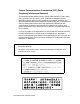
Federal Communications Commission (FCC) Radio Frequency Interference Statement This equipment has been tested and found to comply with the limits for a Class A digital device, pursuant to Part 15 of the FCC Rules. These limits are designed to provide reasonable protection against harmful interference in a commercial installation.
Revision Record Edition or Revision Date First Edition March 2001 Affected Pages/Remarks New Book Part Number: DF1153-E1 ii Drive Module Site Preparation Guide
Contents About This Book .............................................................................................................................. 1 Intended Readers ....................................................................................................................... 1 Content and Organization ......................................................................................................... 2 Terminology Used in This Book .......................................................
Drive Module Cable Requirements ...............................................................................................27 E3300 Interface Cables .............................................................................................................27 SCSI Terminators ................................................................................................................27 FC-1 10x, E2400 10x, FC-1 14x, and E2400 14x Interface Cables .........................................
List of Figures 1 E3300 Drive Module Dimensions ............................................................................................. 13 2 FC-1 10x Drive Module and E2400 10x Command Module Dimensions .............................. 14 3 FC-1 14x Drive Module and E2400 14x Command Module Dimensions .............................. 15 4 Drive Module or E2400 Command Module Airflow ...............................................................
List of Tables 1 Unique Terminology and Concepts .............................................................................................3 2 E3300 Drive Module Weight Table ..............................................................................................7 3 FC-1 10x Drive Module Weight Table .........................................................................................8 4 E2400 10x Command Module Weight Table .....................................................................
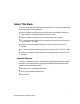
a About This Book This book provides technical specifications and information you will need to prepare a site before installing the following hardware: • E3300 Drive Module containing up to ten drives and one low-voltage-differential- tosingle-ended environmental services monitor (LVD-SE ESM), • • E3300 Drive Module containing up to ten drives and one LVD-LVD ESM • E2400 10x Command Module containing up to ten drives and one or two 2772 controllers • • FC-1 14x Drive Module containing up to fourtee
..............................................................................
. . . . . . . . . . . . . . . . . . . . . . . . . . . . . . . . . . . . . . . . . . . . . . . . . . . . . . . . . . . . . . . . About This Book Table 1 Unique Terminology and Concepts Term Definition Usage Examples canister Portable, removable container for components. Also known as CRU. controller canister command module Compact unit that contains one or two controllers, power supplies, and fans. Note: The E2400 command module also contains disk drives.
.............................................................................. Documentation Set The Drive Module Site Preparation Guide is part of a documentation set that provides planning, installation, operation, and servicing information for SANtricity™ Storage Manager software, command modules (E3300, E4400), drive modules (E3300, FC-1 10x, FC-1 14x) and command modules (E2400 10x, E2400 14x). The documentation set includes: General Documentation • Roadmap.
. . . . . . . . . . . . . . . . . . . . . . . . . . . . . . . . . . . . . . . . . . . . . . . . . . . . . . . . . . . . . . Preparatory Tasks Preparatory Tasks Before starting the installation process, you should complete the following tasks: • Make sure that the installation site meets all area, environmental, and power requirements discussed in this book.
..............................................................................
. . . . . . . . . . . . . . . . . . . . . . . . . . . . . . . . . . . . . . . . . . . . . . . . . . . . . . . . . . . . . . Area Requirements Table 2 E3300 Drive Module Weight Table Unit Maximum1 Unit Weight Empty2 Unit Weight Shipping3 Weight Drive Module, deskside, Low Profile (LP) 18 GB or 36 GB drives 46.4 kg (102.1 lb) 25.95 kg (57.04 lb) 59.0 kg (130.1 lb) Drive Module, deskside, Half Height (HH) 36 GB or 73 GB drives 49.66 kg (109.5 lb) 25.91 kg (57.04 lb) 62.4 kg (137.
.............................................................................. Table 3 FC-1 10x Drive Module Weight Table Unit 8 Maximum Unit Weight1 Empty Unit Weight2 Shipping Weight3 Drive Module, deskside, LP 18 GB or 36 GB drives 44.5 kg (98.0 lb) 23.6 kg (52.0 lb) 59.0 kg (130.0 lb) Drive Module, deskside, HH 36 GB or 73 GB drives 47.8 kg (105.0 lb) 23.6 kg (52.0 lb) 62.4 kg (137.0 lb) Drive Module, rackmount, LP 18 GB and 36 GB drives 38.3 kg (84.4 lb) 12.7 kg (28.0 lb) 43.5 kg (96.
. . . . . . . . . . . . . . . . . . . . . . . . . . . . . . . . . . . . . . . . . . . . . . . . . . . . . . . . . . . . . . Area Requirements Table 4 E2400 10x Command Module Weight Table Unit Maximum Unit Weight1 Empty Unit Weight2 Shipping Weight3 Command Module, deskside, LP 18 GB or 36 GB drives 45.0 kg (99.2 lb) 23.6 kg (52.0 lb) 59.0 kg(130.1 lb) Command Module, deskside, HH 36 GB or 73 GB drives 48.6 kg (107.2 lb) 23.6 kg (52.0 lb) 62.6 kg (138.
.............................................................................. Table 5 FC-1 14x Drive Module Weight Table Unit Drive Module, rackmount, LP 18 GB and 36 GB drives Maximum Unit Weight1 Drive-Ready Unit Weight2 40.02 kg (87.12 lb) 46.94 kg (103.92 lb) 30.5 kg (66.4 lb) LP Drive, 18 GB or 36 GB 1.0 kg (2.2 lb) LP Drive, Blank Canisters 0.32 kg (0.72 lb) ESM 1.67 kg (3.7 lb) Power Supply 2.49 kg (5.5 lb) Fan 1.0 kg (2.2 lb) Shipping Weight3 37.44 kg (83.
. . . . . . . . . . . . . . . . . . . . . . . . . . . . . . . . . . . . . . . . . . . . . . . . . . . . . . . . . . . . . . Area Requirements Table 6 E2400 14x Command Module Weight Table Unit Maximum Unit Weight1 Empty Unit Weight2 Shipping Weight3 Command Module, deskside, LP 18 GB or 36 GB drives 45.0 kg (99.2 lb) 23.6 kg (52.0 lb) 59.0 kg(130.1 lb) Command Module, rackmount, LP 18 GB and 36 GB drives 40.95 kg (90.5 lb) 15.11 kg (33.54 lb) 47.25 kg (105.0 lb) LP Drive, 18 GB or 36 GB 1.
..............................................................................
. . . . . . . . . . . . . . . . . . . . . . . . . . . . . . . . . . . . . . . . . . . . . . . . . . . . . . . . . . . . . . Area Requirements 16.61 cm (6.54 in.) 52.68 cm (20.74 in.) 67.49 cm (26.57 in.) 44.7 cm (17.6 in.) 57.5 cm (22.63 in.) 12.9 cm (5.08 in.) 13.18 cm (5.2 in.) 48.0 cm (18.9 in.) 55.91 cm (22.005 in.) Note: Front panel thickness is 1.59 cm (0.625 in.
.............................................................................. 16.6 cm (6.5 in.) 52.7 cm (20.7 in.) 56.0 cm (22.0 in.) 44.7 cm (17.6 in.) 12.9 cm (5.08 in.) 13.18 cm (5.2 in.) 55.91 cm (22.005 in.) 48.0 cm (18.9 in.) 1.59 cm (0.625 in.
. . . . . . . . . . . . . . . . . . . . . . . . . . . . . . . . . . . . . . . . . . . . . . . . . . . . . . . . . . . . . . Area Requirements 17.60 cm (44.70 in.) 59.74 cm (23.52 in.) 12.9 cm (5.08 in.) 13.23 cm (5.21 in.) 56.13 cm (22.1 in.) 18.97 cm (48.18 in.) 3.63 cm (1.43 in.) Figure 3 FC-1 14x Drive Module and E2400 14x Command Module Dimensions Table 7 Shipping Carton Dimensions Unit Carton Height Carton Width Carton Depth E3300 Deskside and Rackmount 38.1 cm (15.0 in.) 61.4 (24.0 in.
.............................................................................. Airflow Figure 4 shows the airflow direction through a drive module or E2400 command module. Allow at least 2 feet of clearance in front of and behind the drive module for proper ventilation.
. . . . . . . . . . . . . . . . . . . . . . . . . . . . . . . . . . . . . . . . . . . . . . . . . . . . . .
.............................................................................. Table 9 Drive Module and E2400 Command Module Heat Dissipation Unit Heat Dissipation LP 18 GB and 36 GB Drives Heat Dissipation HH 36 GB and 73 GB Drives E3300 673.0 Btu/hr (0.199 kVA or 197.0 W) 826.0 Btu/hr (0.244 kVA or 241.0 W) FC-1 10x 1036.0 Btu/hr (0.31 kVA or 303.0 W) 1070.0 Btu/hr (0.33 kVA or 313.0 W) E2400 10x 1187.0 Btu/hr (0.35 kVA or 347.0 W) 1221.0 Btu/hr (0.37 kVA or 357.
. . . . . . . . . . . . . . . . . . . . . . . . . . . . . . . . . . . . . . . . . . . . . . . . . . . . . . . . . Site Wiring Requirements Site Wiring Requirements Review the following information when preparing the drive module or E2400 command module installation site. • Earth ground – The unit must be properly grounded, including an earth ground conductor on the AC power source.
..............................................................................
. . . . . . . . . . . . . . . . . . . . . . . . . . . . . . . . . . . . . . . . . . . . . . . . . Drive Module Power Requirements Drive Module Power Requirements E3300 Drive Module The AC power source must provide the correct voltage, current, and frequency specified on the manufacturer’s nameplate. Internal AC power units for rackmount cabinets must be able to handle the power requirements for this unit (Table 11). Table 11 E3300 Power Requirements Item Unit of Measure Circuit Breaker 3.
.............................................................................. Power Cord Routing Some rackmount cabinets have two AC distribution boxes. Each AC distribution box has its own power cord. Because of limited space inside the cabinet, it may be easier to connect and route power cords before installing the support rails and command module.
. . . . . . . . . . . . . . . . . . . . . . . . . . . . . . . . . . . . . . . . . . . . . . . . . Drive Module Power Requirements FC-1 10x Drive Module and E2400 10x Command Module The AC power source must provide the correct voltage, current, and frequency specified on the manufacturer’s nameplate. Internal AC power units for rackmount cabinets must be able to handle the power requirements for these units (Table 12).
.............................................................................. Power Cord Routing The drive module and command module use two AC power cords (one for each power supply). You must have an independent AC power source for each power supply in the drive module and command module in order to maintain redundancy. This applies to both deskside and rackmount models. Some rackmount cabinets have two AC distribution boxes. Each AC distribution box has its own power cord.
. . . . . . . . . . . . . . . . . . . . . . . . . . . . . . . . . . . . . . . . . . . . . . . . . Drive Module Power Requirements FC-1 14x Drive Module and E2400 14x Command Module The AC power source must provide the correct voltage, current, and frequency specified on the manufacturer’s nameplate. Internal AC power units for rackmount cabinets must be able to handle the power requirements for these units (Table 13).
.............................................................................. Power Cord Routing The drive module and command module use two AC power cords (one for each power supply). You must have an independent AC power source for each power supply in the drive module and command module in order to maintain redundancy. This applies to both deskside and rackmount models. Some rackmount cabinets have two AC distribution boxes. Each AC distribution box has its own power cord.
. . . . . . . . . . . . . . . . . . . . . . . . . . . . . . . . . . . . . . . . . . . . . . . . . . Drive Module Cable Requirements Drive Module Cable Requirements E3300 Interface Cables The E3300 drive module has two SCSI connectors. To connect the drive module to a SYM1000E command module, you must use 68-pin, VHDCI (very high density cable interface) LVD, Ultra SCSI-2 cables. The maximum length for any SCSI, 68-pin HD cable is 25 m (82 ft.) or 12 m (39 ft.) for VHDCI cable.
.............................................................................. FC-1 10x, E2400 10x, FC-1 14x, and E2400 14x Interface Cables The drive modules and command modules support Fibre Channel connections to the command modules. They have four gigabit interface converter (GBIC) connectors, two on each ESM or controller. The connectors may be fiber optic or copper.
Index A AC power cords E2400 10x 24 E2400 14x 26 E3300 21 E4400 24 FC-1 14x 26 AC power requirements E2400 10x 23 E3300 21 E4400 23 FC-1 14x 25 airflow 16 amperage requirements E2400 10x 23 E2400 14x 25 E3300 21 E4400 23 FC-1 14x 25 B bels, sound power 17 C cable drive interface E2400 10x 28 E2400 14x 28 E3300 27 E4400 28 FC-1 14x 28 Fibre Channel 27, 28 Drive Module Site Preparation Guide host interface E2400 10x 28 E3300 27 E4400 28 FC-1 14x 28 length fiber optic and copper 27, 28 SCSI 27 circuit bre
drive cable connectors 28 weight E2400 10x 9 E2400 14x 11 E3300 7 E4400 8 FC-1 14x 10 drive interface cables E2400 10x 28 E4400 28 FC-1 14x 28 drive interface cablesE3300 27 drive module electrical overload protection 19 installation 5 E earth ground 19 electrical circuit breakers 19, 21, 23, 25 copper wire 28 current 21, 23, 25 earth ground 19 frequency 21, 23, 25 operating current 21, 23 overload protection 19 power requirements E2400 10x 23 E2400 14x 25 E3300 21 E4400 23 FC-1 14x 25 single-phase wiring
F fan E2400 10x 9 E2400 14x 11 E3300 7 E4400 8 FC-1 14x 10 FC-1 14x airflow 16 circuit breaker type 25 dimension 15 interface cables 28 noise level 17 power cords 26 power requirements 25 weight 10 wiring for 19 fiber optic cable length 27, 28 order information 27, 28 Fibre Channel cable 27, 28 fuse requirements 21, 23, 25 installation host adapters 5 preparation tasks 5 interface cables drive E2400 10x 28 E2400 14x 28 E3300 27 E4400 28 FC-1 14x 28 host E2400 10x 28 E2400 14x 28 E3300 27 E4400 28 FC-1 14x
P S power connections E2400 14x 26 E3300 21 E4400 22, 24 FC-1 14x 26 interruptions 19 overload protection 19 redundancy E2400 10x 24 E2400 14x 26 E3300 21, 22 E4400 24 FC-1 14x 26 power cord E2400 10x 24 E2400 14x 26 E3300 22 E4400 24 FC-1 14x 26 number of 21 power supply E2400 10x 9 E2400 14x 11 E3300 7 E4400 8 FC-1 14x 10 preparing command module for installation 5 pressure (sound) 17 SCSI bus 27 SCSI cables maximum length 27 shortwave laser 28 single-phase wiring 20 sound 17 specifications airflow 16
V VHDCI (very high density cable interface) 27 voltage E2400 10x 19, 23 E2400 14x 19, 25 E3300 19, 21 E4400 19, 23, 25 FC-1 14x 19, 25 W weight E2400 10x 9 E2400 14x 11 E3300 7 E4400 8 FC-1 14x 10 table of 8, 10 wiring earth ground 19 single-phase 20 Drive Module Site Preparation Guide Index-5
Index-6 Drive Module Site Preparation Guide