
User's Manual


. . . . . . . . . . . . . . . . . . . . . . . . . . . . . . . . . . . . . . . . . . . . . . . . . . . . . . . . . Site Wiring Requirements
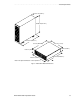
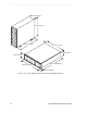
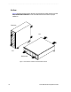
Drive Module Site Preparation Guide 19
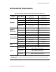
Site Wiring Requirements
Review the following information when preparing the drive module or E2400 command
module installation site.
•
Earth ground – The unit must be properly grounded, including an earth ground
conductor on the AC power source.
•
Circuit overloading – Make sure the power circuits and associated circuit breakers in
the cabinet and building provide sufficient power and overload protection. To prevent
possible damage to the unit, isolate its power source from large switching loads (such as
air conditioning motors).
•
Power interruptions – The drive module or E2400 command module will withstand
the following applied voltage interruptions:
•
Input transient: 50% of nominal voltage
•
Duration: one half cycle
•
Minimum frequency: once every 10 seconds
•
Power failures – Once power is restored after a complete power failure, the unit
automatically performs a power-up recovery sequence without operator intervention.
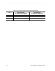
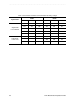
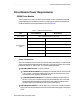
Site Wiring and Voltages
The drive modules and E2400 command module use wide-ranging, redundant power
supplies that automatically match voltages to the AC power source. They are a 120/220
VAC, 50/60 Hz units that meet standard voltage requirements for both domestic (USA)
and international (outside USA) operation. They use standard industrial wiring with a
line-to-neutral or line-to-line power connections (Table 10).