USER’S GUIDE Embedded SATA Software RAID for ICH6R October 2004 ® DB15-000319-00
Document DB15-000319-00, October 2004 This document describes the initial release of LSI Logic Corporation’s Embedded SATA Software RAID for ICH6R and will remain the official user’s guide for all revisions/releases of this product until rescinded by an update. LSI Logic Corporation reserves the right to make changes to any products herein at any time without notice.
TRADEMARK ACKNOWLEDGMENT LSI Logic, the LSI Logic logo design, and MegaRAID, are trademarks or registered trademarks of LSI Logic Corporation. Linux is a trademark of Linus Torvalds. Red Hat is a trademark of Red Hat, Inc. MS-DOS, Windows, and Windows NT are registered trademarks of Microsoft Corporation. Novell and NetWare are registered trademarks of Novell, Inc. All other brand and product names may be trademarks of their respective companies. To receive product literature, visit us at http://www.
iv Copyright © 2004 by LSI Logic Corporation. All rights reserved.
Preface Package Contents You should have received the following: • a Embedded SATA Software RAID for ICH6R User's Guide • software license agreement • CD/diskette(s) with the software for Embedded SATA Software RAID This book is the primary reference and user’s guide for the Embedded SATA Software RAID for ICH6R. Customer specific documentation may be included as well.
• Chapter 3, BIOS Configuration Utility, explains how to configure ICH6R SATA and arrays, assign RAID levels, plan the array configuration, optimize storage, and use the ICH6R IDE Setup Utility. • Chapter 4, Operating System Installation, contains the procedures for installing the Windows 2000, 2003, and XP, Red Hat Linux, SuSE Linux, and Novell NetWare operating systems when using the Embedded SATA Software RAID.
Notation Example Meaning and Use vertical dots . . . Vertical dots indicate that a portion of a program or listing has been omitted from the text. semicolon and other punctuation Use as shown in the text. Preface Copyright © 2004 by LSI Logic Corporation. All rights reserved.
viii Preface Copyright © 2004 by LSI Logic Corporation. All rights reserved.
1.1 1.2 2.1 2.2 2.3 3.1 3.2 3.3 3.4 3.5 3.6 3.7 3.8 4.1 4.2 4.3 RAID Benefits 1-1 1.1.1 Improved I/O 1-1 1.1.2 Increased Reliability 1-2 Product Features 1-2 1.2.1 SATA Ports 1-2 1.2.2 BIOS Features 1-2 1.2.3 Driver Features 1-3 1.2.4 Manageability/Disk Console 1-4 RAID 0 2-1 RAID 1 2-2 RAID 10 2-3 Configuring Arrays 3-1 Configuration Strategies 3-2 Assigning RAID Levels 3-2 Performing a Quick Configuration 3-3 Configuring Arrays and Logical Drives 3-4 3.5.
4.4 5.1 5.2 5.3 5.4 5.5 6.1 6.2 6.3 6.4 6.5 7.1 7.2 4.3.4 SuSE Linux 9.0 Driver Installation on a New System 4-6 4.3.5 SuSE 8.2 Driver Installation 4-7 4.3.6 SuSE SLES8 Driver Installation 4-8 Novell NetWare Driver Installation 4-8 4.4.1 Novell NetWare Driver Files Description 4-8 4.4.2 New Novell NetWare System Driver Installation 4-8 4.4.3 Existing Novell NetWare System Driver Installation 4-10 General Description 5-1 Installing HyperCFG 5-2 Using HyperCFG 5-2 Configuration File 5-8 5.4.
3.1 3.2 3.3 5.1 5.2 7.1 7.2 Physical Drives Required per RAID Level Physical Drives Required per RAID Level Logical Drive Parameters and Descriptions HyperCFG Options and Attributes Return Codes on Error Conditions Problems and Suggested Solutions Embedded SATA Software RAID Problem Report Form 3-2 3-3 3-5 5-3 5-10 7-1 7-3 xi Copyright © 2004 by LSI Logic Corporation. All rights reserved.
xii Copyright © 2004 by LSI Logic Corporation. All rights reserved.
2.1 2.2 2.3 3.1 3.2 3.3 6.1 RAID 0 Array RAID 1 Array RAID 10 Array Configuration Menu Screen Logical Drive Configuration Screen Logical Drive Submenu Control Panel Screen 2-2 2-2 2-3 3-6 3-7 3-10 6-2 xiii Copyright © 2004 by LSI Logic Corporation. All rights reserved.
xiv Copyright © 2004 by LSI Logic Corporation. All rights reserved.
Chapter 1 Overview This manual describes the Embedded SATA Software RAID for ICH6R. This chapter provides an overview of this product and contains the following sections: • Section 1.1, “RAID Benefits,” page 1-1 • Section 1.2, “Product Features,” page 1-2 The Embedded SATA Software RAID supports four Serial ATA ports, providing a cost-effective way to achieve higher transfer rates and reliability. Embedded SATA Software RAID supports 1.
1.1.2 Increased Reliability The electromechanical components of a disk subsystem operate more slowly, require more power, and generate more noise and vibration than electronic devices. These factors reduce the reliability of data stored on disks. RAID 1 and RAID 10 systems improve data storage reliability and fault tolerance compared to single-drive computers. The additional drive in each RAID 1 array makes it possible to prevent data loss from a hard drive failure.
1.2.3 • ability to select a logical drive as boot device • support for power-on self test (POST) Memory Management (PMM) for the BIOS memory requirement (Specification v1.01, November 21, 1997) • enhanced disk drive support (Specification 2.9, revision 08, March 12, 1998) • Industry-standard EBDA • Self-monitoring analysis and reporting technology (S.M.A.R.T.
1.2.
Chapter 2 RAID Levels Embedded SATA Software RAID supports RAID levels 0, 1, and 10. These RAID levels are discussed in the following sections: 2.1 • Section 2.1, “RAID 0,” page 2-1 • Section 2.2, “RAID 1,” page 2-2 • Section 2.3, “RAID 10,” page 2-3 RAID 0 RAID 0 (Figure 2.1) provides disk striping across all configured drives in the RAID subsystem. RAID 0 does not provide any data redundancy, but does offer the best performance of any RAID level.
Figure 2.1 RAID 0 Array Segment 1 Segment 3 Segment 5 Segment 7 2.2 Segment 2 Segment 4 Segment 6 Segment 8 RAID 1 RAID 1 (Figure 2.2) duplicates all data from one drive to a second drive. RAID 1 provides complete data redundancy, but at the cost of doubling the required data storage capacity. Uses Databases or any other mission critical environment that requires fault tolerance. Strong Points Provides complete data redundancy. RAID 1 is ideal for any application that requires fault tolerance.
2.3 RAID 10 RAID 10 is a combination of RAID 1 and RAID 0. RAID 10 has mirrored drives. It breaks up data into smaller blocks, then stripes the blocks of data to each RAID 1 RAID set. Each RAID 1 RAID set then duplicates its data to its other drive. The size of each block is determined by the stripe size parameter, which is set during the creation of the RAID set. RAID 10 can sustain one drive failure in each array while maintaining data integrity.
2-4 RAID Levels Copyright © 2004 by LSI Logic Corporation. All rights reserved.
Chapter 3 BIOS Configuration Utility This chapter explains how to configure ICH6R SATA and arrays, assign RAID levels, plan the array configuration, optimize storage, and use the ICH6R IDE Setup Utility. This information is presented in the following sections: 3.1 • Section 3.1, “Configuring Arrays,” page 3-1 • Section 3.2, “Configuration Strategies,” page 3-2 • Section 3.3, “Assigning RAID Levels,” page 3-2 • Section 3.4, “Performing a Quick Configuration,” page 3-3 • Section 3.
3.2 Configuration Strategies You have two choices when creating a RAID array. • Maximizing Fault Tolerance You can maximize fault tolerance to protect against loss of data by using mirroring. Use mirror configuration (RAID 1) to attain this objective. • Maximizing Logical Drive Performance You can maximize logical drive performance by using striping. Select striping configuration (RAID 0) to attain this objective.
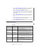
The factors you need to consider when selecting a RAID level are listed in Table 3.2. Table 3.2 Physical Drives Required per RAID Level Level Description and Use Pros Cons Number Fault of Drives Tolerant 0 Data divided in blocks and distributed sequentially (pure striping). Use for non-critical data that requires high performance. High data throughput for large files No fault tolerance. Data is lost if a drive fails. One to four 1 Data duplicated on another disk (mirroring).
3.5 Configuring Arrays and Logical Drives This section provides detailed instructions for configuring the logical disks and arrays. 3.5.1 Starting the BIOS Configuration Utility During bootup, the following BIOS banner displays the following: Press Ctrl-M to run LSI Logic Embedded SATA RAID Setup Utility Hold down the key while you press . The main menu for the utility displays. 3.5.2 Selecting a Configuration Method Section 3.5.
3.5.3.2 Logical Drive Parameters For the logical drive you can change the RAID level and stripe size. Table 3.3 contains descriptions of the logical drive parameters. Table 3.3 Logical Drive Parameters and Descriptions Parameter Description RAID Level The number of physical drives in a specific array determines the RAID levels that can be implemented with the array. RAID 0 requires one or two physical drives. RAID 1 requires exactly two physical drives. RAID 10 requires exactly four physical drives.
Figure 3.1 Step 2. Configuration Menu Screen Press the spacebar to associate the selected physical drives with the current array. The indicator for the selected drives changes from READY to ONLIN A[array number]-[drive number]. For example, ONLIN A1-3 means array 1 with disk drive 3. Step 3. Press after you finish creating the current array. Step 4. Press to select configurable arrays. Step 5. Press the spacebar to select the array.
Figure 3.2 Step 6. Logical Drive Configuration Screen Set the RAID level for the logical drive by highlighting RAID and pressing . The available RAID levels for the current logical drive display. Step 7. Select a RAID level and press . Step 8. Set the RAID logical drive size and stripe size. Step 9. When you have defined the current logical drive, select Accept and press . Step 10. Repeat step 7 to step 10 to configure additional logical drives. Step 11.
configuration. If you do not want to delete the existing configuration data, use View/Add Configuration. Perform the following steps to configure a disk array using New Configuration or View/Add Configuration: Step 1. Select Configure→ View/Add Configuration from the CU Management Menu. The CU displays an array selection window. Step 2. Select the physical drives to include in the array by pressing the arrow keys to select specific physical drives. Step 3.
3.5.4 Initializing Logical Drives You can initialize the logical drives using individual initialization, which initializes a single logical disk. There are two methods to initialize a logical drive using the individual initialization procedure using the CU. For the first method, perform the following steps to initialize a logical drive using the Initialize menu. Step 1. On the Management Menu, select Initialize. Step 2. Use the space bar to highlight the logical drive to initialize.
Figure 3.3 Logical Drive Submenu Step 2. Select a logical drive, if there is more than one configured. and press . Step 3. Select Initialize from the submenu and press . Step 4. Select Yes at the prompt and press . The CU displays a bar graph showing the initialization progress. Step 5. When initialization completes, press to return to the previous menu.
The indicators for the selected drive changes to REBLD. Step 5. When rebuild is complete, press any key to continue. Step 6. Press to display the Management Menu. A second way to perform a manual rebuild on an individual drive is as follows: 3.6.1 Step 1. Select the option from the CU→ Objects→ Physical Drive submenu. Step 2. Press the arrow keys to select the physical drive to be rebuilt and press . Step 3.
Note that the logical drive should be at a RAID 1 level to start check consistency. If you select a RAID 0 logical drive, a message displays stating that a check consistency cannot be performed. To de-select a logical drive, press the space bar again. Step 3. Press . Step 4. At the prompt, select Yes to start check consistency and press . If you press while the check consistency is in progress, the following options display: 3.
Step 11. Press to exit the CU and reboot. Step 12. Set the host system to boot from the drive. Some operating systems treat RAID storage adapters as mass storage devices. Using a Pre-loaded System Drive Copyright © 2004 by LSI Logic Corporation. All rights reserved.
3-14 BIOS Configuration Utility Copyright © 2004 by LSI Logic Corporation. All rights reserved.
Chapter 4 Operating System Installation This chapter contains the procedures for installing the Windows 2000, 2003, and XP, Red Hat Linux, SuSE Linux, and Novell NetWare operating systems when using the Embedded SATA Software RAID. The chapter contains the following sections: 4.1 • Section 4.1, “Windows 2000/2003/XP Driver Installation,” page 4-1 • Section 4.2, “DOS Driver Installation,” page 4-3 • Section 4.3, “Linux Driver Installation,” page 4-3 • Section 4.
4.1.1 Step 5. Scroll down the list until the appropriate selection for your system which contains the Embedded SATA Software RAID and for your operating system displays, then click . Step 6. Continue with the normal installation procedure. Updating the Windows 2000/2003/XP Driver Perform the following steps to update the Windows 2000 or 2003 driver or install the Windows 2000 or 2003 driver into an existing system booted from a standard IDE drive. Step 1. Click the Windows Start button.
Step 1. Click the Windows Start button. The Windows menu displays. Step 2. Select Settings. The Settings menu displays to the right. Step 3. Click Control Panel. The Control Panel window displays. Step 4. Select Adapters. Step 5. Select the Drivers tab. The controller appears in the list as LSI Logic Embedded SATA Controller. Step 6. Select the Devices tab. One or more entries display as LSI Logic Embedded SATA #xx under LSI Logic Embedded SATA Controller. 4.
4.3.2 Preparing the Installation Disk(s) for Linux This section describes how to prepare the installation disk(s) from the obtained driver image files using the Windows- or Linux-based operating systems. Refer to this section when necessary during installation of Windows and Linux operating systems. 4.3.2.1 Using a Windows Operating System Under Windows, you can use the rawrite floppy image writer utility to create disk images from image files. The image writer can be downloaded from the Internet.
4.3.2.2 Using a Linux Operating System Under Red Hat and SuSE Linux, you can use a driver diskette utility to create disk images from image files. Perform the following steps create the driver update disk: Step 1. Copy the driver update disk image dud-.img to a Linux system. Step 2. Insert a blank floppy diskette into the floppy drive. Step 3. Confirm that the files are in the selected directory. Step 4.
4.3.4 Step 7. Follow the Red Hat Linux installation procedure to complete the installation. Step 8. Reboot the system. SuSE Linux 9.0 Driver Installation on a New System This section describes the fresh installation of a Linux SuSE 9.0 system with the Embedded Software RAID Stack. Prepare installation disks with the driver image, then perform the following steps to install the driver: Step 1. Boot your system using the SuSE 9.0 CD 1. Step 2.
Step 9. Select Yes and complete the installation Important: After all the selected packages are installed, a prompt displays and gives you 10 seconds to reply. If you do not reply within 10 seconds, you will have to start the installation process over. Step 10. Select Stop before the 10 seconds are up. Step 11. Press . This opens a terminal you can use to run a script. Step 12. At the prompt, type: cd update/000/install Step 13. Press . Step 14. Next, type: ./update.post Step 15.
4.3.6 SuSE SLES8 Driver Installation This section describes a fresh installation on a Linux SuSE SLES8.0 system with the Embedded Software RAID Stack. Prepare installation disks with the driver image, then perform the following steps to install the driver: 4.4 Step 1. Create a RAID array using the BIOS. Step 2. Boot your system using the SuSE SLES8 1.0 Disk 1. Step 3. When the first screen displays, press and select the installation menu option. Step 4.
Step 3. Highlight Default using the arrow keys, then press to change the option to Manual. Step 4. Highlight Continue and press . The screen used to prepare the boot partition displays. Step 5. Highlight Free Space, then press . Step 6. Accept the default (500 MB) or modify as desired, then press . Step 7. Highlight Continue, then press . The Server Settings screen displays. You can modify the settings before going to the next screen. Step 8.
Step 18. Press twice. Step 19. Select Continue and press . The storage devices and driver names display so you can match the drivers to the hardware devices. Step 20. Select Continue and press . Step 21. Select Continue and press again. The message “Loading driver” displays, then the screen Create Sys Volume displays. Step 22. Select Create and press . The Main Menu displays. Step 23. Select Continue Installation and press .
This completes the procedure. If you choose Select an Additional Driver, the Select a Driver screen displays. Perform the following steps to select an additional driver. Step 1. Press , then follow the instructions that appear. Step 2. Insert a diskette into the A:/ drive and press . The system finds the driver and installs it. Novell NetWare Driver Installation Copyright © 2004 by LSI Logic Corporation. All rights reserved.
4-12 Operating System Installation Copyright © 2004 by LSI Logic Corporation. All rights reserved.
Chapter 5 Hyper Configuration Utility HYPERCFG is a command line utility for ICH6R software. This chapter details the product features in these sections: 5.1 • Section 5.1, “General Description,” page 5-1 • Section 5.2, “Installing HyperCFG,” page 5-2 • Section 5.3, “Using HyperCFG,” page 5-2 • Section 5.4, “Configuration File,” page 5-8 • Section 5.5, “Return Codes on Error Condition,” page 5-10 General Description HYPERCFG is a command line utility for SATA RAID.
5.2 Installing HyperCFG Perform the following steps to install HyperCFG: Step 1. Copy the HyperCFG executable file from the CD to your hard drive. The filename in the various operating systems is: Step 2. – HYPERCFG.exe for DOS – hypercfg for Linux – HyperWin.exe for Windows Run the file from the hard drive. The HyperCFG utility displays. Use the options in Section 5.3, “Using HyperCFG” to set the RAID configuration and other options. 5.
Table 5.1 HyperCFG Options and Attributes Options Description /S Silent Operation. When this option is set, the utility does not prompt the user. /F[File Name] This option redirects the output to the specified filename. If the filename is not specified, then the filename defaults to HyperCFG.CFG. /L [/C][/D] [/B[Filename]] Displays the configuration sector of the specified drive Using only /L displays the configuration sector from the first available drive.
Table 5.1 HyperCFG Options and Attributes (Cont.) Options Description /A[Array] (for new configuration) This option is used to configures arrays for RAID 0, 1, and 10 :d1, d2...dn /G: or is the RAID mode for configuring. The field can be any of the following three options. m=S[n] Means the arrays are configured as RAID 0. S[n] equals stripe size.
Table 5.1 HyperCFG Options and Attributes (Cont.) Options Description Free Array Information /freearr/a:d1, d2, dn... Force a Physical /pdstate /d Drive Online or / Offline Adapter Information /adp /c This option is used to access the free array information. /freearr/a Specifies the free array information option. Specifies the RAID level you need to create. d1, d2, dn... Lists the drives. This option is used to force a physical drive online or offiline.
Table 5.1 HyperCFG Options and Attributes (Cont.) Options Description Adapter Properties /SetADP /C [/r] [/d] [/b] [/s] [/n] [/f] [/c] [/ars] [/boot] [/arb] 5-6 This option is used to select values for adapter properties. /SetADP Specifies the adapter properties option. /C Specifies the controller number. [/r Specifies the rebuild rate for the controller. is from 0 - 100%. This setting is optional.
Table 5.1 Options HyperCFG Options and Attributes (Cont.) Description Display Options This option determines how the data displays. This option is valid only for /I. /W[o] Prints the dump for the /I option. The [o] field can be either of the following: V Prints the dump in Verbose mode Default option: If [o] is not specified, then data displays as a HEX dump. /F Redirects the output to a file ‘fn’ (for filename). The default filename is hypercfg.bin. /Y[x][fn] Logs to the given filename ‘fn’.
Table 5.1 HyperCFG Options and Attributes (Cont.) Options Description /M[R/][ This option sets the maximum user-accessible sector address for the /C][/D] specified drive. The address is specified in hexadecimal format. /Mr Miscellaneous Options Resets the maximum address to the native maximum address of the specified drive. This attribute is reserved for miscellaneous options. /S Executes in Silent mode. /V Detects the presence of RAID BIOS and displays the BIOS version.
The valid choices for the OPTIONS field are as follows: • WRITE_CACHE (sets the type of write policy) • VIRUS_PROTECTION (selects virus protection) • DMA_ENABLED (enables direct memory access) A “+” prefix to the option value sets the option and a “-” resets the option. 5.4.
Drives other than those specified in the configuration file are configured as SPARE DRIVES. To force configuration of a SPARE DRIVE, do not include that drive in the configuration file. That drive will be automatically configured as SPARE. 5.5 Return Codes on Error Condition Table 5.2 lists the return codes that display when there are errors and provides the descriptions of those errors. Table 5.
Table 5.2 Return Codes on Error Conditions Return Code Description 1Bh RAID BIOS not found. Occurs with a /V command if the RAID BIOS is not found. 1Ch Feature not available in IDE drive. This error occurs if the /P or /M command is used on drives that do not support this feature or if invalid parameters are specified. 1. Note: Other error codes are reserved. Return Codes on Error Condition Copyright © 2004 by LSI Logic Corporation. All rights reserved.
5-12 Hyper Configuration Utility Copyright © 2004 by LSI Logic Corporation. All rights reserved.
Chapter 6 Spy Service This chapter describes the Spy Service program and contains the following sections • Section 6.1, “Starting or Stopping Spy Service under Windows 2000, XP, or 2003,” page 6-1 • Section 6.2, “Installing Spy Service under Linux,” page 6-3 • Section 6.3, “Installing and Running Spy Service under Novell NetWare,” page 6-3 • Section 6.4, “Uninstalling Spy Service,” page 6-4 • Section 6.
Figure 6.1 Control Panel Screen Step 2. Click on Administrative Tools→ Services icon→ Spy Ser. A dialog window displays with the start and stop options. Step 3. Click on the Start or Stop button. This starts or stops the Spy Service program, depending on your selection. Note: 6-2 You can right-click on the Spy Service icon and select “Stop Spy” to stop the Spy program. The Spy icon displays on the right side of the taskbar. See Section 6.5, “Spy Service Icon” for more information about the icon.
6.2 Installing Spy Service under Linux Perform the following steps to install Spy Service under Linux. Spy Service runs in the background after installation. Note: You must have “GNOME” libraries installed before you install Spy Service. Step 1. Log in to GUI mode. Step 2. At the Linux prompt, type: $ rpm -ivh spy.x.x.x.i386.rpm Step 3. Press . The rpm is extracted and the necessary files installed and started, 6.
6.4 Uninstalling Spy Service Perform the following steps to uninstall Spy Service. Step 1. Stop the Spy Service program. See “Section 6.1, “Starting or Stopping Spy Service under Windows 2000, XP, or 2003” for instructions on stopping Spy Service. Step 2. Click on Start→ Control Panel. The Control Panel displays. Step 3. Click on Add/Remove Programs. The list of currently installed programs displays. Step 4. 6.5 Click on the Spy Service program and select Remove.
Do the following to place the Spy icon on the Taskbar when operating under Windows 2000: Click on Start→ Programs→ MegaRAID IDE→ MegaRAID IDE Spy. This places the Spy icon on the Taskbar. Note: The Spy icon displays on the Taskbar automatically under the Windows Server 2003 operating system. Spy Service Icon 6-5 Copyright © 2004 by LSI Logic Corporation. All rights reserved.
6-6 Spy Service Copyright © 2004 by LSI Logic Corporation. All rights reserved.
Chapter 7 Troubleshooting 7.1 Problems and Suggested Solutions Table 7.1 describes possible problems you might encounter, along with suggested solutions. Table 7.1 Problems and Suggested Solutions Problem Suggested Solution • Make sure that the cable ends are connected properly. • Make sure that the power cables to the drives are connected OR properly. • Change cables. The system hangs when the adapter ROM for Embedded SATA Software RAID scans • If everything fails, change the drive(s).
Table 7.1 Problems and Suggested Solutions Problem Suggested Solution One of the hard drives in a mirrored (RAID Replace the failed drive with another drive that has the same or 1) array has failed. greater capacity. You insert a new drive with no Press any key to enter the BIOS Configuration Utility (Ctrl-M) to configuration into the slot which is already configure the new drive. Mark the drive as one of the following: part of a mirrored (RAID 1) array.
Table 7.
7-4 Troubleshooting Copyright © 2004 by LSI Logic Corporation. All rights reserved.
Customer Feedback We would appreciate your feedback on this document. Please copy the following page, add your comments, and fax it to us at the number shown. If appropriate, please also fax copies of any marked-up pages from this document. Important: Please include your name, phone number, fax number, and company address so that we may contact you directly for clarification or additional information. Thank you for your help in improving the quality of our documents.
Reader’s Comments Fax your comments to: LSI Logic Corporation Technical Publications M/S E-198 Fax: 408.433.4333 Please tell us how you rate this document: Embedded SATA Software RAID User’s Guide. Place a check mark in the appropriate blank for each category.